
Verona L6-2.5L (2005)
Data Link Connector: Testing and Inspection
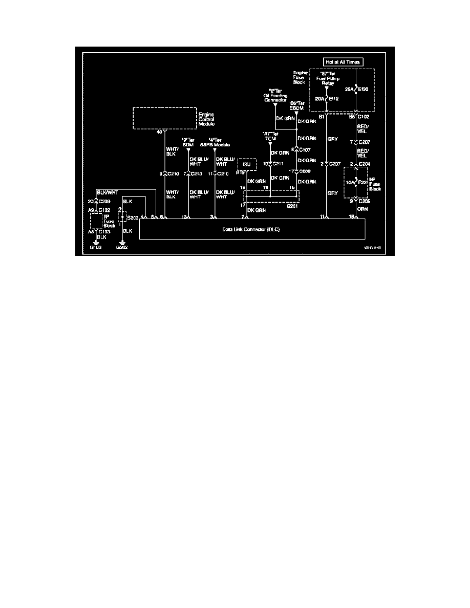
Data Link Connector Diagnosis
Wiring Diagram
Circuit Description
The provision for communicating with the Engine Control Module (ECM) is the Data Link Connector (DLC). It is located under the instrument panel.
The DLC is used to connect the scan tool. Battery power and ground is supplied for the scan tool through the DLC. The Class II serial data circuit to the
DLC allows the ECM to communicate with the scan tool. A Universal Asynchronous Receiver Transmitter (DART) serial data line is used to
communicate with the other modules such as the Electronic Brake Control Module (EBCM), the Supplemental Inflatable Restraint (SIR) system and the
Instrument Panel Cluster (IPC).