
XL-7 2WD V6-3.6L (2007)
Oil Pressure Warning Lamp/Indicator: Testing and Inspection
Engine Oil Pressure Indicator Malfunction
Diagnostic Instructions
^
Perform the [Diagnostic System Check - Vehicle Diagnostic Information] prior to using this diagnostic procedure.
^
Review [Strategy Based Diagnosis] for an overview of the diagnostic approach. See: Testing and Inspection/Initial Inspection and Diagnostic
Overview/Strategy Based Diagnosis
^
[Diagnostic Procedure Instructions - Vehicle Diagnostic Information] provides an overview of each diagnostic category. See: Testing and
Inspection/Initial Inspection and Diagnostic Overview/Diagnostic Procedure Instructions - Vehicle Diagnostic Information
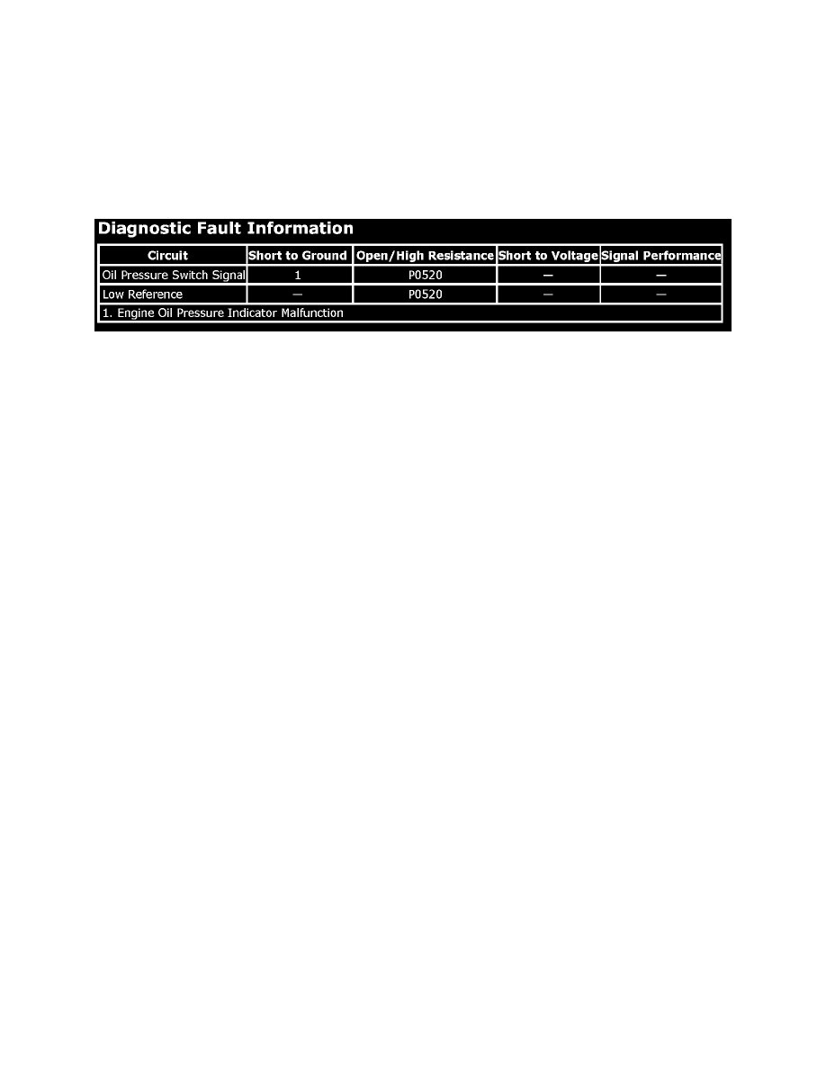
Diagnostic Fault Information
Circuit/System Description
The engine oil pressure (EOP) switch is a normally closed switch that opens with the proper oil pressure. With the ignition switch turned ON and the
engine not running, the engine control module (ECM) should detect a low signal voltage input. With the engine running, the pressure switch opens, and
the ECM should detect a high signal voltage input.
Circuit/System Verification
Ignition ON, engine running, verify the scan tool Engine Oil Pressure Switch parameter is OK.
^
If not the specified value, refer to [Oil Pressure Diagnosis and Testing]. See: Engine, Cooling and Exhaust/Engine/Testing and
Inspection/Component Tests and General Diagnostics/Oil Pressure Check
Circuit/System Testing
NOTE: Do not turn the key to the crank position or engage the starter at any time during diagnosis.
1. Ignition OFF, disconnect the harness connector at the engine oil pressure (EOP) switch.
2. Ignition OFF, test for less than 1 ohm of resistance between the low reference circuit terminal B and ground.
^
If greater than the specified range, test the low reference circuit for an open/high resistance. If the circuit tests normal, replace the ECM.
3. Ignition ON, verify the scan tool Engine Oil Pressure Switch parameter is OK.
^
If not the specified value, test the signal circuit terminal A for a short to ground. If the circuit tests normal, replace the ECM.
4. Ignition ON, install a 3 A fused jumper wire between the signal circuit terminal A and the low reference circuit terminal B. Verify the scan tool
Engine Oil Pressure Switch parameter is Low.
^
If not the specified value, test the signal circuit for an open/high resistance. If circuit test normal, replace the ECM.
5. If all circuits test normal, test or replace the engine oil pressure switch.
Repair Instructions
Perform the [Diagnostic Repair Verification - Vehicle Diagnostic Information] after completing the diagnostic procedure. See: Testing and
Inspection/Diagnostic Trouble Code Tests and Associated Procedures
^
[Engine Oil Pressure Sensor and/or Switch Replacement]
^
[Control Module References] for ECM or IPC replacement, setup, and programming. See: Testing and Inspection/Programming and Relearning