
XL-7 2WD V6-3.6L (2007)
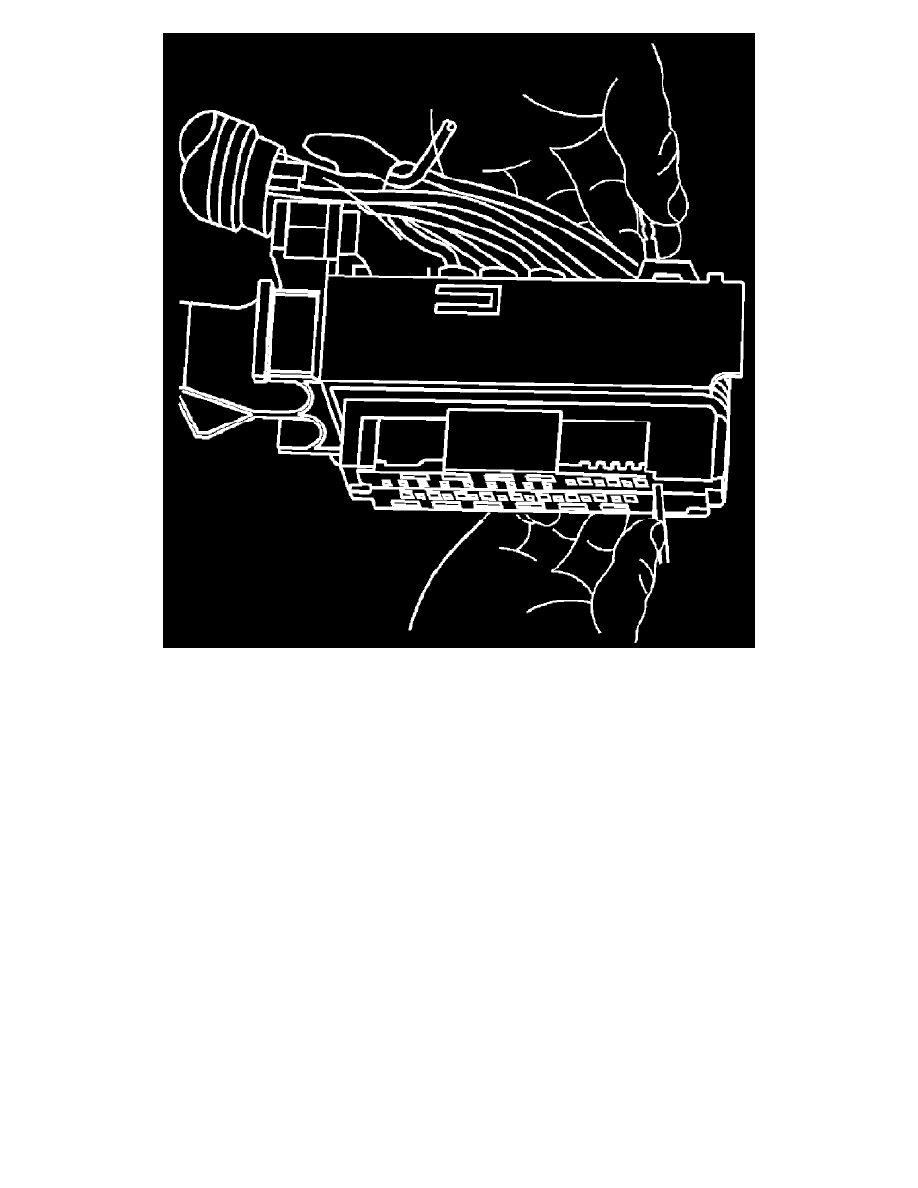
6. Insert the J 38125-12A (GM P/N 12094429) into the corresponding terminal release cavity. The release cavities are the 2 center rows of cavities
on one half of the connector.
7. Pressing the J 38125-12A (GM P/N 12094429) tool in the release cavity of the terminal you are removing, gently pull the wire out of the back of
the connector. Always remember never use force when pulling a terminal out of a connector. See the release tool cross reference in the Reference
Guide of the J-38125 to ensure that the correct release tool is used.
Terminal Repair Procedure
Use the appropriate terminal and crimper in the J-38125 in order to replace the terminal.
Tyco/AMP Connectors (Door Module)
Tyco/AMP Connectors (Door Module)
Special Tool
J-38125 Terminal Repair Kit
Removal Procedure