
XL-7 2WD V6-3.6L (2007)
^
A wire stripping tool
^
J 38125-8 Crimping Tool (GM P/N 12085115)
^
J 38125-5 Ultra Torch Special Tool (GM P/N 12085116)
The DuraSeal splice sleeves have the following 2 critical features:
^
A special heat shrink sleeve environmentally seals the splice. The heat shrink sleeve contains a sealing adhesive inside.
^
A cross hatched (knurled) core crimp provides necessary contact integrity for the sensitive, low energy circuits.
The J-38125 also serves as a generic terminal repair kit. The kit contains the following items:
^
A large sampling of common electrical terminals
^
The correct tools in order to attach the terminals to the wires
^
The correct tools in order to remove the terminals from the connectors
GMLAN Repairs
NOTE: When making a repair to any GMLAN network, the original wire length after the repair must be the same length as before the repair. If the
network is a twisted pair, the twist must be maintained after the repair is completed.
GMLAN has 2 types of networks, low speed and high speed. Low speed GMLAN has a single wire and works at slow speeds. High speed GMLAN has 2
wires in a twisted pair and works at higher speeds. For more information on GMLAN, refer to Data Link Communications Description and Operation.
GMLAN Connector Terminal Repair
NOTE: A service terminal can be used to replace damaged connector terminals for both high speed and low speed GMLAN systems. When making a
connector terminal repair on a GMLAN high speed system with twisted pair wires, do not untwist the wires more than necessary to make the repair.
The terminals in the GMLAN system are made of a special metal. This metal provides the necessary contact integrity for the sensitive, low energy
circuits. These terminals are available in the J-38125. If the individual terminals are damaged on any GMLAN connection, use the appropriate connector
repair procedure in order to repair the terminal. Refer to Connector Repairs for the appropriate connector repair procedure. See: Diagrams/Diagnostic
Aids/Connector Repairs
GMLAN Wire Repair
NOTE: Refer to Wiring Repairs in order to determine the correct wire size for the circuit you are repairing. You must obtain this information in order to
ensure circuit integrity. See: Diagrams/Diagnostic Aids/Wiring Repairs
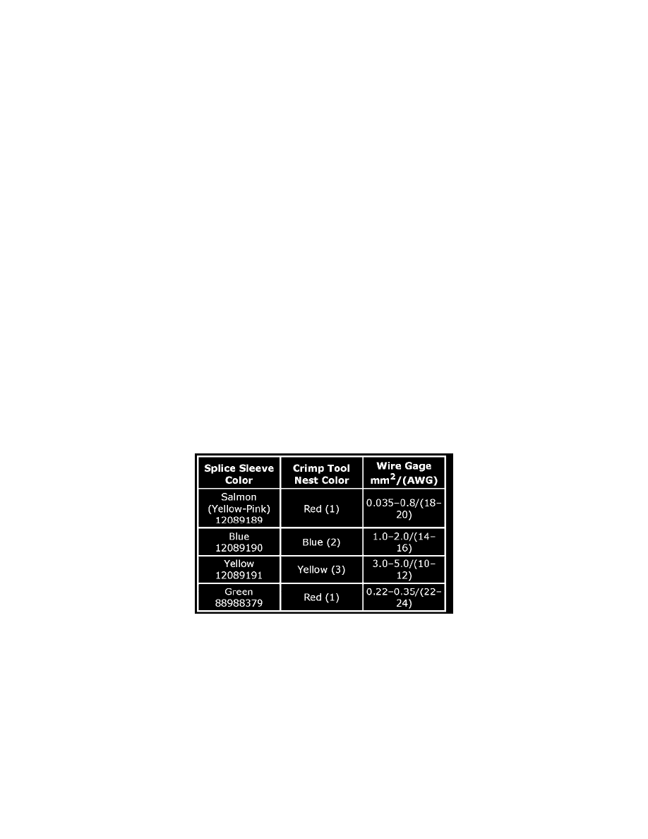
If a wire is damaged, repair the wire by splicing in a new section of wire of the same gage size (0.5 mm, 0.8 mm, 1.0 mm, etc.). Use the DuraSeal splice
sleeves and splice crimping tool from the J-38125. Use the following wiring repair procedures in order to ensure the integrity of the sealed splice.
NOTE: You must perform the following procedures in the listed order. Repeat the procedure if any wire strands are damaged. You must obtain a clean
strip with all of the wire strands intact.
1. Open the harness by removing any tape:
^
Use a sewing seam ripper (available from sewing supply stores) in order to cut open the harness in order to avoid wire insulation damage.
^
Use the DuraSeal splice sleeves on all types of insulation except coaxial.
^
Do not use the DuraSeal splice sleeve to form a splice with more than 2 wires coming together.
2. Cut as little wire off the harness as possible. You may need the extra length of wire in order to change the location of a splice.
Adjust splice locations so that each splice is at least 40 mm (1.5 in) away from the other splices, harness branches, or connectors.
3. Strip the insulation: