
XL-7 2WD V6-3.6L (2007)
Heated Glass Element: Testing and Inspection
Rear Window Defogger Malfunction
Diagnostic Instructions
^
Perform the [Diagnostic System Check - Vehicle Diagnostic Information] prior to using this diagnostic procedure. See: Testing and
Inspection/Initial Inspection and Diagnostic Overview/Diagnostic System Check - Vehicle Diagnostic Information
^
Review [Strategy Based Diagnosis] for an overview of the diagnostic approach.See: Testing and Inspection/Initial Inspection and Diagnostic
Overview/Strategy Based Diagnosis
^
[Diagnostic Procedure Instructions - Vehicle Diagnostic Information] provides an overview of each diagnostic category.See: Testing and
Inspection/Initial Inspection and Diagnostic Overview/Diagnostic Procedure Instructions - Vehicle Diagnostic Information
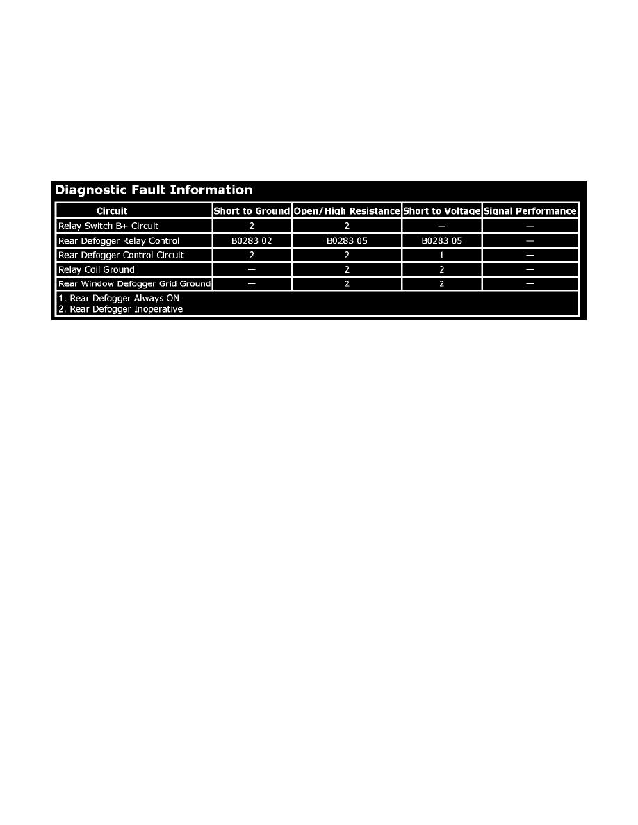
Diagnostic Fault Information
Circuit/System Description
When you depress the rear defogger button, voltage is supplied to the DEFOG relay coil and the HVAC control module also illuminates the rear window
defogger indicator. Battery positive voltage is supplied at all times to the DEFOG relay switched input and the DEFOG relay coil is always grounded.
This allows battery positive voltage from the relay switched input through the switch contacts and out the relay switched output to the rear window
defogger. Ground for the rear defogger grid is provided by G401.
When you start the engine and press the rear defogger switch for the first time, the defogger cycle lasts for 15 minutes. Further operation results in 7.5
minute defogger cycles. The defogger cycle resets to 15 minutes when you cycle the ignition to the OFF position and then to the ON position.
Circuit/System Verification
1. Ignition ON, observe the operation of the Rear Defogger Grid while pressing the Rear Defogger Switch. The Rear Defogger Grid should
ACTIVATE and DEACTIVATE when changing between commanded states.
2. Command the rear window defogger indicator ON and OFF with the scan tool. The rear window defogger indicator should turn ON and OFF when
changing between the commanded states.
^
If the Defogger Indicator does not illuminate, replace the HVAC control module.
Circuit/System Testing
1. Ignition OFF, disconnect the REAR DEFOG relay.
2. Ignition OFF, test for less than 1.0 ohm of resistance between the relay coil ground circuit terminal 25 and ground.
^
If greater than the specified range, test for an open/high resistance.
3. Ignition ON, verify that a test lamp does not illuminate between the relay controlled output circuit terminal 46 and ground.
^
If the test lamp illuminates, test the control circuit for a short to voltage.
4. Verify that a test lamp illuminates between the relay switch B+ circuit terminal 43 and ground.
^
If the test lamp does not illuminate, test the B+ circuit for a short to ground or an open/high resistance. If the circuit tests normal and the RR
DEFOG circuit fuse is open, test the relay controlled output circuit terminal 46 for a short to ground.
5. Ignition OFF, disconnect the harness connectors C1 and C2 at the Rear Defogger Grid.
6. Ignition OFF, test for less than 1.0 ohm of resistance between the Rear Defogger Grid ground circuit terminal 1 and ground.
^
If greater than the specified range, test the ground circuit for an open/high resistance.
7. Connect the harness connectors at the Rear Defogger Grid.
8. Ignition ON, connect a 30-A fused jumper wire between the relay switch B+ circuit terminal 43 and the relay controlled output circuit terminal 46.
Verify the Rear Defogger Grid is activated.
^
If the Rear Defogger Grid does not activate, test the control circuit for an open/high resistance. If the circuit tests normal, test or replace the
Rear Defogger Grid.
9. Connect a test lamp between the relay coil control circuit terminal 39 and the relay coil ground circuit terminal 25.