
XL-7 Limited 4WD V6-2.7L (2002)
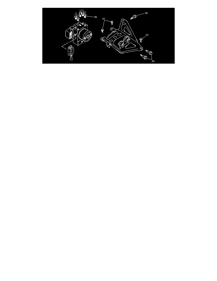
1. Install hydraulic unit/control module assembly by reversing removal procedure.
Tightening torque
Brake pipe flare nut (a): 16 Nm (1.6 kgf-m, 11.5 ft. lbs.)
ABS hydraulic unit/control module assembly bolt (b): 9 Nm (0.9 kgf-m, 6.5 ft. lbs.)
Bracket bolt (c): 10 Nm (1.0 kgf-m, 7.5 ft. lbs.)
2. Bleed air from brake system.
3. Check each installed part for fluid leakage and perform "ABS Hydraulic Unit Operation Check:".
NOTE: For new ABS hydraulic unit/control module assembly, if "ABS Hydraulic Unit Operation Check: " procedure has not been performed,
"ABS" warning lamp may flash when ignition switch is turned ON position.
Accordingly perform "ABS Hydraulic Unit Operation Check: " to stop flashing of ABS warning lamp.