
XL-7 Limited 4WD V6-2.7L (2002)
Wheel Speed Sensor: Testing and Inspection
Sensor Output Voltage
Front
Output Voltage Inspection
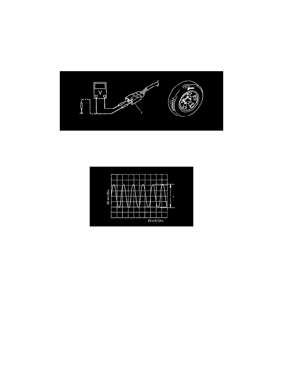
1. Turn ignition switch to "OFF" position.
2. Hoist vehicle a little.
3. Disconnect connector (1) of wheel speed sensor.
4. Connect voltmeter between connector terminals.
5. While turning wheel at a speed of approximately 2/3 to 1 full rotation per second, check AC voltage of sensor. If measured voltage is not as
specified, check sensor, rotor and their installation conditions.
Output AC voltage at 2/3 to one rotation per second (35 - 53 Hz) (Front wheel speed sensor) 106 mV or more
Reference
When using oscilloscope for this check, check if peak-to-peak voltage (1) meets specification and waveform is complete.
Peak-to-peak voltage at 2/3 to one rotation per second (35 - 53 Hz) (Front wheel speed sensor) 150 mV or more
Rear
Output Voltage Inspection
Check in the same procedure as that used of front wheel speed sensor check.
Output AC voltage at 2/3 to one rotation per second (25 - 38 Hz) (Rear wheel speed sensor) 106 mV or more
Reference
When using oscilloscope, peak-to-peak voltage at 2/3 to one rotation per second (25 - 38 Hz) (Rear wheel speed sensor) 150 mV or more