
XL-7 Limited 4WD V6-2.7L (2002)
Shift Interlock Solenoid: Description and Operation
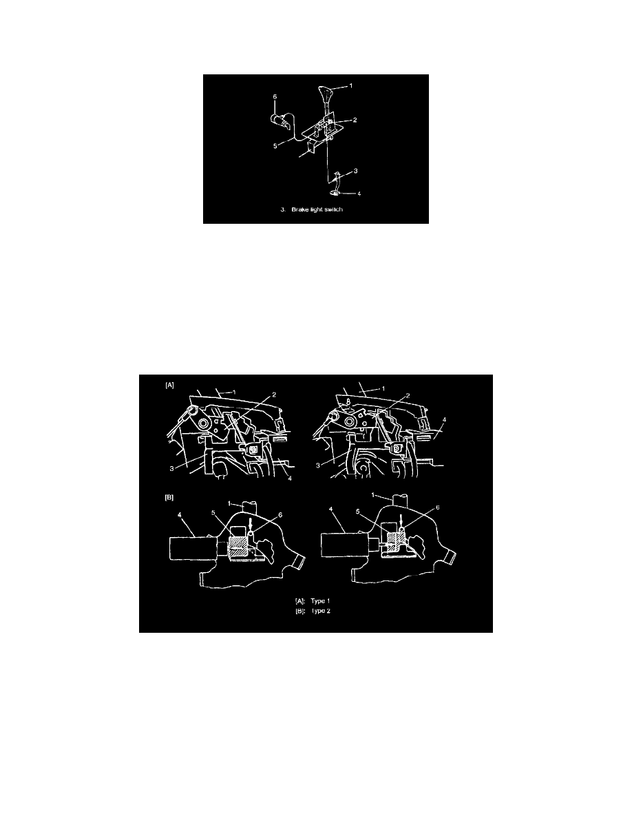
Shift Lock Solenoid Control
This system consists of shift lock solenoid (2) control system and interlock cable (5) control system.
The shift lock solenoid (2) control system is so designed that the selector lever (1) can not be shifted from "P" range position unless the ignition switch
(6) is turned ON and the brake pedal is depressed. And the interlock cable (5) control system is so designed that the selector lever (1) cannot be shifted
from "P" range position unless the ignition switch (6) is turned to "ACC" or "ON" position. Also, the ignition key cannot be pulled out of the key slot
unless the selector lever (1) is in "P" range.
Shift Lock Solenoid Control Operations
When the select lever (1) is in "P" range, the ignition key position is "ON" and depressing the brake pedal cause the electric current to flow to the
solenoid. As the shift lock solenoid rod (3) (or the lock plate (5)) is drawn toward the solenoid (4)in this state, it frees the interlock cam (2) (or the
detent pin (6)), which then allows the select lever (1) to be shifted from "P" range to any other position.
Even when the select lever (1) is in "P" range, if the ignition key position is "LOCK" or "ACC" or the brake pedal is not depressed, the electric current
does not flow to the solenoid (4).
In this state, the shift lock solenoid rod (3) (or the lock plate (5)) is pushed away from the solenoid (4) by spring force and it obstructs the interlock
cam (2) (or the detent pin (6)) movement. Thus the select lever button does not work even when pressed and the select lever (1) shift is prevented.