
XL-7 Standard 2WD V6-2.7L (2001)
3.
-
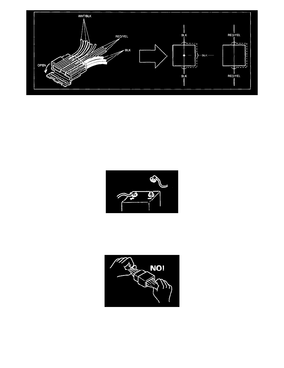
Wiring of this vehicle uses joint connectors (J/C) which divide one wire into several different wires or combine several different wires into one
wire.
-
The pin numbers for joint connectors are omitted because all the same color wires are connected with each other inside the joint connectors,
the structure of which can be seen by opening the connector head as shown.
-
The joint connectors is illustrated.
Precautions
CAUTIONS IN SERVICING
When performing works related to electric Systems, observe following cautions for the purpose of protection of electrical parts and prevention of a fire
from occurrence.
-
When removing the battery from the vehicle or disconnecting the cable from the battery terminals for inspection or service works on the electric
Systems, always confirm first that the ignition switch and all the other switches have been turned OFF. Otherwise, the semi-conductor part may be
damaged.
-
When disconnecting cables from the battery, be sure to disconnect the one from the negative (-) terminal first and then the other from the positive
(+) terminal.
-
Reverse the above order when connecting the cables to the battery terminals.
-
When disconnecting connectors, never pull the wiring harnesses. Unlock the connector lock first and then pull them apart by holding connectors
themselves.