
XL-7 Standard 4WD V6-2.7L (2002)
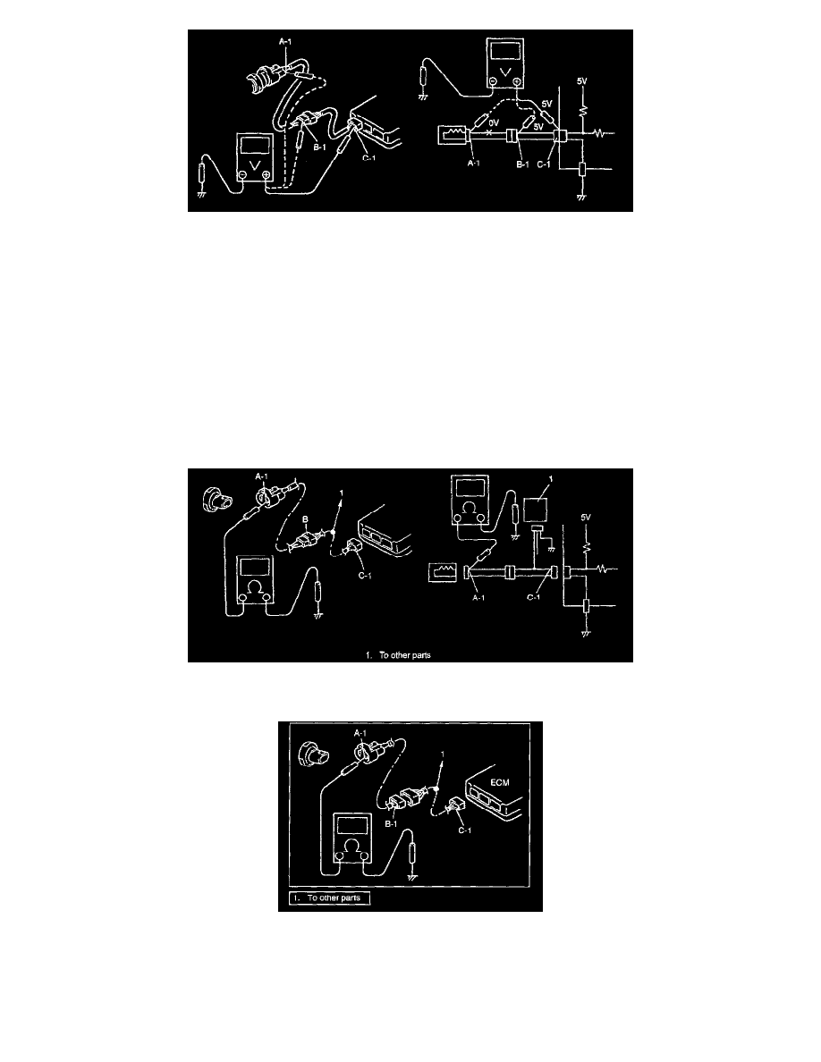
b. Also, if measured values were as listed below, it means that there is a resistance (abnormality) of such level that corresponds to the voltage
drop in the circuit between terminals "A-1" and "B-1".
Voltage between
"C-1" and body ground: Approx. 5 V
"B-1" and body ground: Approx. 5 V
"A-1" and body ground: Approx. 3 V
"A-1" and "B-1": 2 V voltage drop
Short Circuit Check (Wire Harness to Ground)
1. Disconnect negative cable from battery.
2. Disconnect connectors at both ends of the circuit to be checked.
NOTE:
If the circuit to be checked is connected to other parts (1), disconnect all connectors of those parts. Otherwise, diagnosis will be misled.
3. Measure resistance between terminal at one end of circuit ("A-1" terminal in figure) and body ground. If continuity is indicated, it means that there
is a short to ground between terminals "A-1" and "C-1" of the circuit.
4. Disconnect the connector included in circuit (connector B) and measure resistance between "A-1" and body ground. If continuity is indicated, it
means that the circuit is shorted to the ground between terminals "A-1" and "B-1".
Intermittents and Poor Connection
Most intermittent are caused by faulty electrical connections or wiring, although a sticking relay or solenoid can occasionally be at fault. When checking
it for proper connection, perform careful check of suspect circuits for:
-
Poor mating of connector halves, or terminals not fully seated in the connector body (backed out).