
XL-7 Touring 4WD V6-2.7L (2002)
15. Remove throttle body from intake collector.
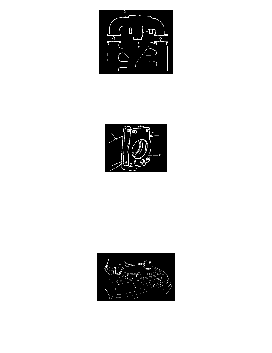
NOTE:
^
TP sensor (4), or other components containing rubber must not be placed in a solvent or cleaner bath. A chemical reaction will cause these
parts to swell, harden or get distorted.
^
Don't out drills or wires into Passages for cleaning. It causes damages in passages.
Installation
1. Clean mating surfaces and install throttle body gasket to intake collector (1) with new gasket (2).
2. Install throttle body to intake collector and tighten bolts.
3. Connect PCV hose.
4. Install throttle body and intake collector to intake manifold with new intake collector gaskets.
5. Install EGR pipe with new gaskets.
6. Connect breather hose and EVAP canister purge valve hose and install PCV valve to cylinder head.
7. Connect connectors of EVAP canister purge valve, MAP sensor and EGR valve.
Fix wire harness with clamps.
8. Install clamp bracket to intake collector.
9. Connect ground wire connector.
10. Connect connectors of TP sensor, ground and IAC valve.
11. Install surge tank pipe to intake manifold with new gaskets and intake air pipe to throttle body. Install surge tank cover.
12. Connect engine coolant hoses to throttle body.
13. Connect accelerator cable and A/T throttle cable (A/T).
14. Install strut tower bar (1) and tighten bolts.
15. Refill cooling system.
16. Connect negative (-) cable at battery.
17. Adjust accelerator cable and A/T throttle cable.
Cleaning