
Camry CE Sedan 4-Door L4-2164cc 2.2L DOHC MFI (1997)
A 4 or B 19-Ground:
Continuity with Driver's Door Lock cylinder unlocked with key
A 3 or B 18-Ground:
Continuity with Driver's, Front Passenger's Door lock cylinder locked with key
D 12, D 13 DOOR COURTESY SW FRONT LH, RH
1-Ground:
Closed with each door open
D 16, D 17 DOOR KEY LOCK AND UNLOCK SW FRONT LH, RH
1-2:
Closed with Door Lock Cylinder locked with key
1-3:
Closed with door Lock Cylinder unlocked with key
D 19, D 20 DOOR LOCK MOTOR AND DOOR UNLOCK DETECTION SW FRONT LH, RH
1-4:
Closed with unlock position
U 1 UNLOCK WARNING SW
1-2:
Closed with Ignition Key in cylinder
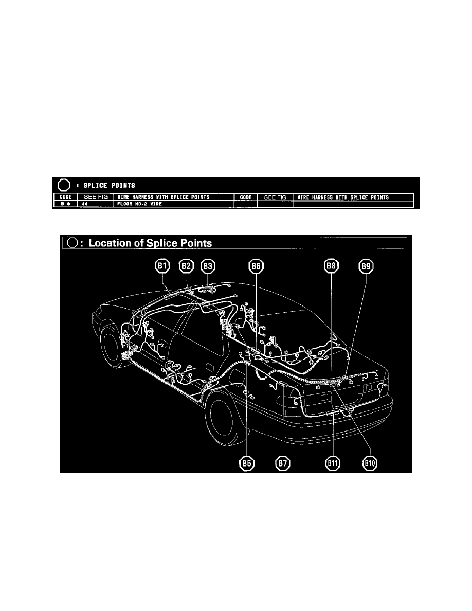
Splice Points
Splice Points
Location Of Splice Points (Fig 44)
System Outline
Current always flows to TERMINAL A 13 (W/O Theft Deterrent System), B 1 (W/ Theft Deterrent System) of the Integration Relay through the
DOOR fuse.
When the Ignition SW is turned ON, the current flowing through the GAUGE fuse flows to TERMINAL 7 of the Integration Relay --> Terminal A 12
(W/O Theft Deterrent System), B 3 (W/ Theft Deterrent System) --> the Power Relay (coil side) --> GROUND.
1. MANUAL LOCK OPERATION
When the Door Lock Control SW or Door Key Lock and Unlock SW are operated to LOCK position, a lock signal is input to TERMINAL A 1
or A 3 (W/O Theft Deterrent System), B 6 or B 18 (W/ Theft Deterrent System) of the Integration Relay and causes the relay to function. Current
flows from TERMINAL A 13 (W/O Theft Deterrent System), B 1 (W/ Theft Deterrent System) of the relay --> TERMINAL A 6 (W/O Theft