
Camry CE Sedan 4-Door L4-2164cc 2.2L DOHC MFI (1997)
VTA-E2:
0.3-0.8 Volts with the Throttle Valve fully closed
3.2-4.9 Volts with the Throttle Valve fully opened
VC-E2:
4.5-5.5 Volts
OD2-E1:
9.0-14.0 Volts with the O/D Main SW turned ON
0-3.0 Volts with the O/D Main SW turned OFF
+B-E1:
9.0-14.0 Volts
E 3-A, E 4-B ELECTRONICALLY CONTROLLED TRANSMISSION SOLENOID
A-1, B-1, B-3-Ground: Each 11-15 Ohms
O 2 O/D MAIN SW
2-4:
Closed with the O/D Main SW OFF, open with the O/D Main SW ON
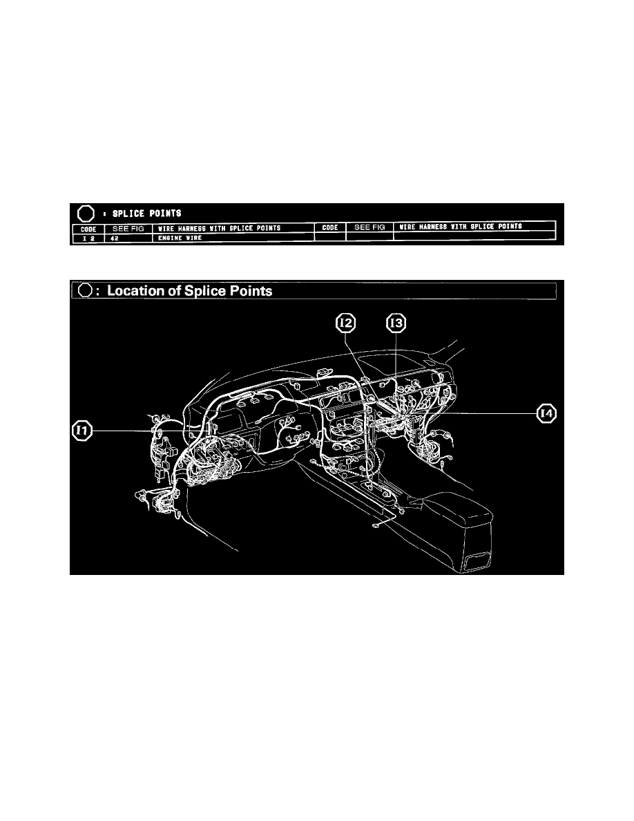
Splice Points
Splice Points
Location Of Splice Points (Fig 42)
System Outline
Previous Automatic Transmissions have selected each gear shift using mechanically controlled throttle hydraulic pressure, governor hydraulic pressure,
and lock-up hydraulic pressure. The Electronically Controlled Transmission, however, electrically controls the line pressure and lock-up pressure etc.,
through the solenoid valve. Engine Control Module controls of the solenoid valve based on the input signals from each Sensor which makes smooth
driving possible by shift selection for each gear which is most appropriate to the driving conditions at that time.
1. GEAR SHIFT OPERATION
During driving, the Engine Control Module selects the shift for each Gear which is most appropriate to the driving conditions, based on input
signals from the Engine Coolant Temp. Sensor to TERMINAL THW of the Engine Control Module, and also the input signals to TERMINAL
SPD of the Engine Control Module from the Vehicle Speed Sensor devoted to the Electronically Controlled Transmission. Current is then output
to the Electronically Controlled Transmission Solenoid. When Shifting to 1st speed, current flows from TERMINAL S1 of the Engine Control
Module --> TERMINAL B-3 of the Solenoid --> GROUND, and continuity to the No.1 Solenoid causes the shift.
For 2nd speed, the current flows from TERMINAL S1 of the Engine Control Module to TERMINAL B-3 of the Solenoid --> GROUND, and
from TERMINAL S2 of the Engine Control Module to TERMINAL B-1 of the Solenoid --> GROUND, and continuity to Solenoids No.1 and
No.2 causes the shift.