
Camry XLE Sedan 4-Door L4-2164cc 2.2L DOHC MFI (1997)
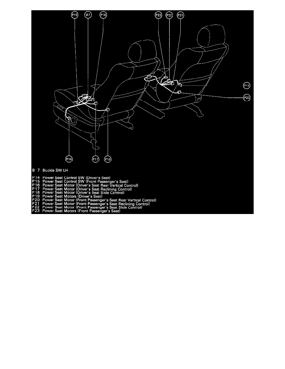
Position Of Parts In Seat (Fig 34)
Service Hints
B 6, B 7 BUCKLE SW
1-2:
Closed with driver's seat belt in use
D12 DOOR COURTESY SW FRONT LH
1-Ground: Closed with LH door open
U1 UNLOCK WARNING SW
1-2:
Closed with Ignition Key in Cylinder
INTEGRATION RELAY
10-Ground: Always continuity
6-Ground: Continuity with the driver's door open
5-Ground: Continuity with the Ignition Key in Cylinder
8-Ground: Continuity with the driver's seat belt in use
1-Ground: Always approx. 12 Volts
System Outline
Current always flows to TERMINAL 1 of the Integration Relay through the DOME fuse.
1. SEAT BELT WARNING SYSTEM
When the Ignition SW is turned ON, current flows from the GAUGE fuse to TERMINAL 7 of the Integration Relay. At the same time, current
flows to TERMINAL 9 of the relay from the GAUGE fuse through the Seat Belt Warning Light. This current activates the Integration Relay and