
Camry XLE Sedan 4-Door L4-2164cc 2.2L DOHC MFI (1997)
Vehicle Speed Sensor: Description and Operation
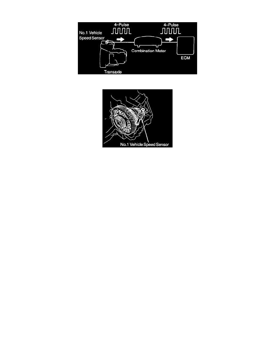
Sensor Signal Flow
Sensor Location
CIRCUIT DESCRIPTION
The No.1 vehicle speed sensor outputs a 4-pulse signal for every revolution of the rotor shaft, which is rotated by the transmission output shaft via
the driven gear. After this signal is converted into a more precise rectangular waveform by the waveform shaping circuit inside the combination
meter, it is then transmitted to the ECM. The ECM determines the vehicle speed based on the frequency of these pulse signals.