
Camry XLE Sedan 4-Door L4-2164cc 2.2L DOHC MFI (1997)
Ignition Coil: Diagnostic Trouble Code Tests and Associated Procedures
DTC P1300 Igniter No. 1 Circuit Malfunction
DTC P1300 Igniter No. 1 Circuit Malfunction
CIRCUIT DESCRIPTION
The ECM determines the ignition timing, turns on Tr1 at a predetermined angle (°CA) before the desired ignition timing and outputs and ignition
signal (IGT) 1 to the igniter.
Since the width of the IGT signal is constant, the dwell angle control circuit in the igniter determines the time the control circuit starts primary
current flow to the ignition coil based on the engine rpm and ignition timing one revolution ago, that is, the time the Tr2 turns on.
When it reaches the ignition timing, the ECM turns Tr1 off and outputs the IGT signal 0.
This turns Tr2 off, interrupting the primary current flow and generating a high voltage in the secondary coil which causes the spark plug to spark.
Also, by the counter electromotive force generated when the primary current is interrupted, the igniter sends an ignition confirmation signal (IGF)
to the ECM. The ECM stops fuel injection as a fail safe function when the IGF signal is not input to the ECM.
DETECTING CONDITION
HINT: Ignition coil No.1 is for cylinder No.1 and No.4, and ignition coil No.2 is for cylinder No.2 and No.3.
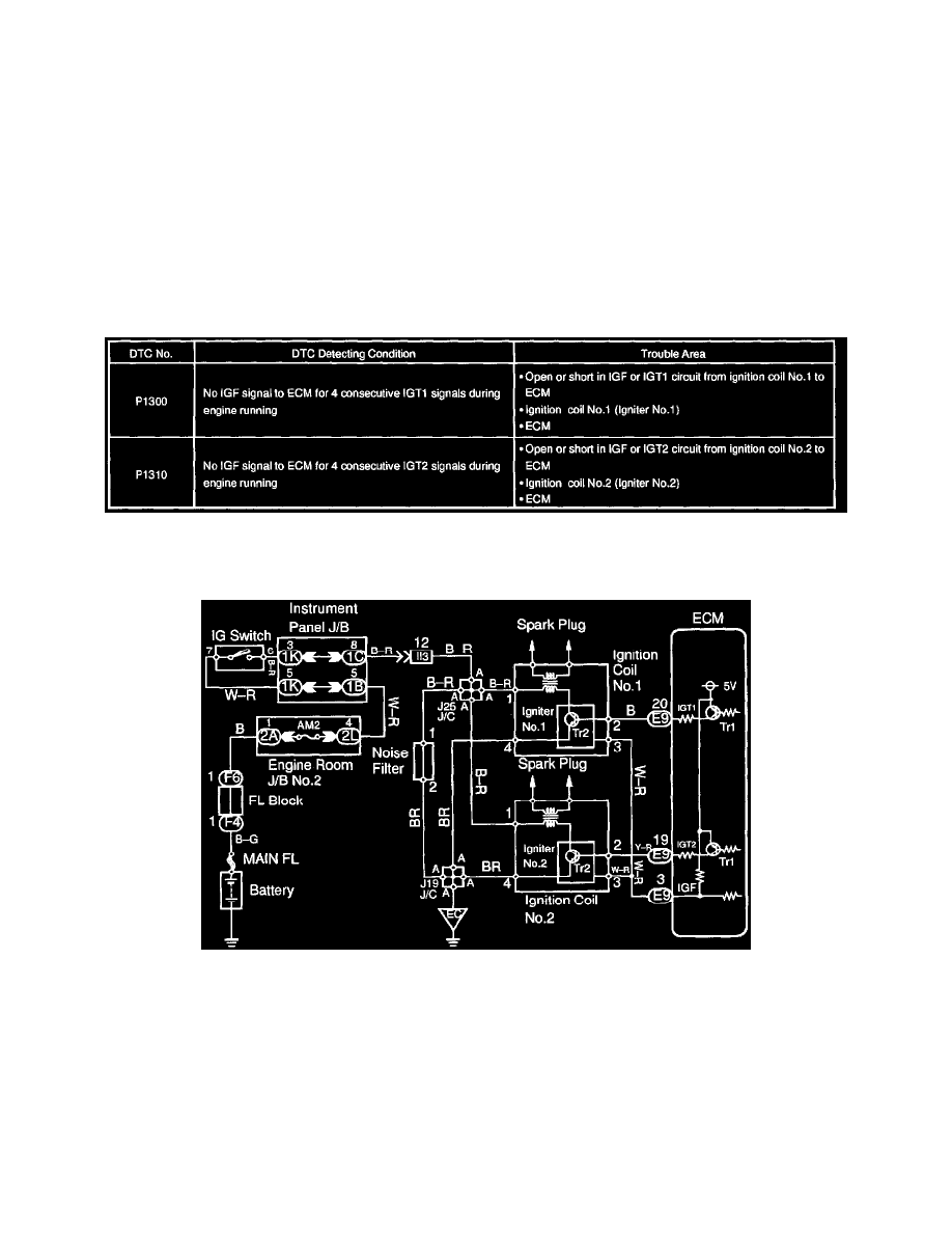
WIRING DIAGRAM