
Camry XLE Sedan 4-Door L4-2164cc 2.2L DOHC MFI (1997)
Step 3
INSPECTION PROCEDURE
Tc Terminal Circuit
Tc Terminal Circuit
CIRCUIT DESCRIPTION
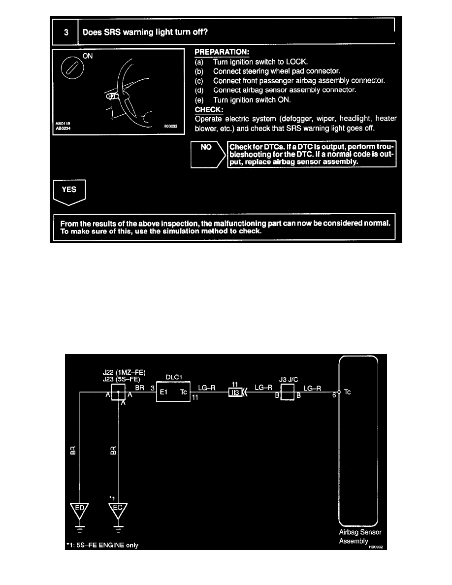
By connecting terminals Tc and E1 of the DLC1 the airbag sensor assembly is set in the DTC output mode. The DTCs are displayed by the
blinking of the SRS warning light.
WIRING DIAGRAM