
Camry XLE Sedan 4-Door L4-2164cc 2.2L DOHC MFI (1997)
Intake Air Temperature Sensor: Description and Operation
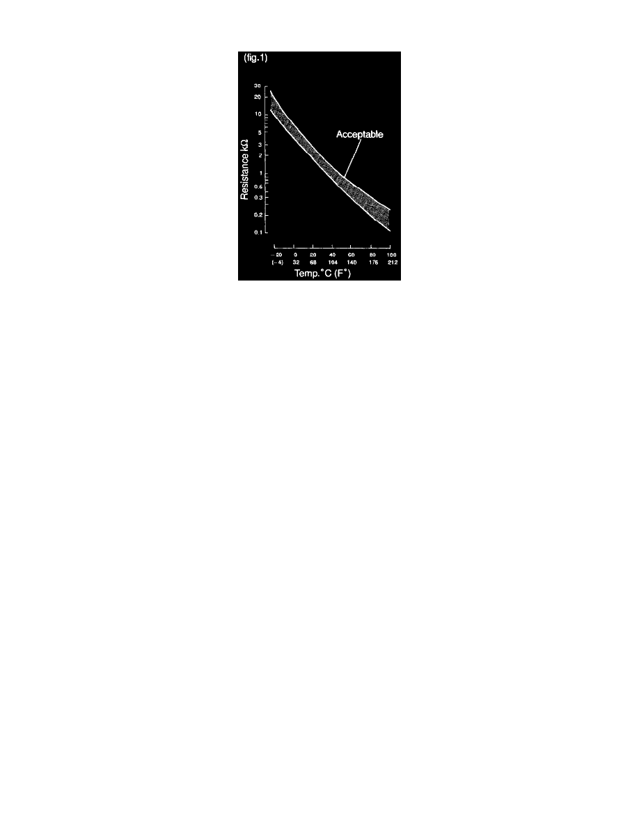
Figure 1
CIRCUIT DESCRIPTION
A thermistor built in the sensor changes the resistance value according to the intake air temp., The lower the intake air temp., the greater the
thermistor resistance value, and the higher the intake air temp., the lower the thermistor resistance value (See fig.1).
The air intake temp. sensor is connected to the ECM (See below). The 5V power source voltage in the ECM is applied to the intake temp. sensor
from the terminal THA via a resistor R.
That is, the resistor R and the intake air temp. sensor are connected in series. When the resistance value of the intake air temp. sensor changes in
accordance with changes in the intake air temp., the potential at terminal THA also changes. Based on this signal, the ECM increases the fuel
injection volume to improve driveability during cold engine operation.