
Corolla CE Sedan 4-Door L4-1587cc 1.6L DOHC MFI (1997)
Oxygen Sensor: Description and Operation
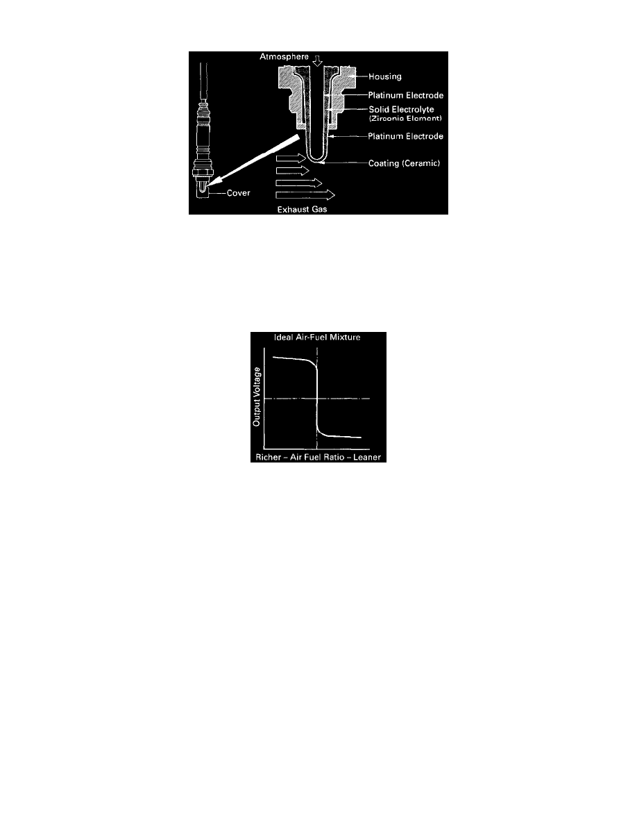
Oxygen Sensor Cut-Away
CIRCUIT DESCRIPTION
To obtain a high purification rate for the CO, HC and NOx components of the exhaust gas, a three-way catalytic converter is used, but for the most
efficient use three-way catalytic converter, the air-fuel ratio must be precisely controlled so that it is always close to the stoichiometric air-fuel
ratio
The oxygen sensor has the characteristic whereby its Output voltage changes suddenly in the vicinity of the stoichiometric air-fuel ratio. This
characteristic is used to detect the oxygen concentration in the exhaust gas and provide feedback to the computer for control of the air-fuel ratio.
Oxygen Sensor Output Voltage Chart
When the air-fuel ratio becomes LEAN, the oxygen concentration in the exhaust increases and the oxygen sensor informs the ECM of the LEAN
condition (small electromotive force: 0V).
When the air-fuel ratio is RICHER than the stoichiometric air-fuel ratio the oxygen concentration in the exhaust gas is reduced and the oxygen
sensor informs the ECM of the RICH condition (large electromotive force: 1V).
The ECM judges by the electromotive force from the oxygen sensor whether the air-fuel ratio is RICH or LEAN and controls the injection time
accordingly. However, if malfunction of the oxygen sensor causes out- put of abnormal electromotive force, the ECM is unable to perform
accurate air-fuel ratio control.