
Corolla LE Sedan L4-1762cc 1.8L DOHC MFI (1998)
Vapor Pressure Sensor: Testing and Inspection
INSPECTION
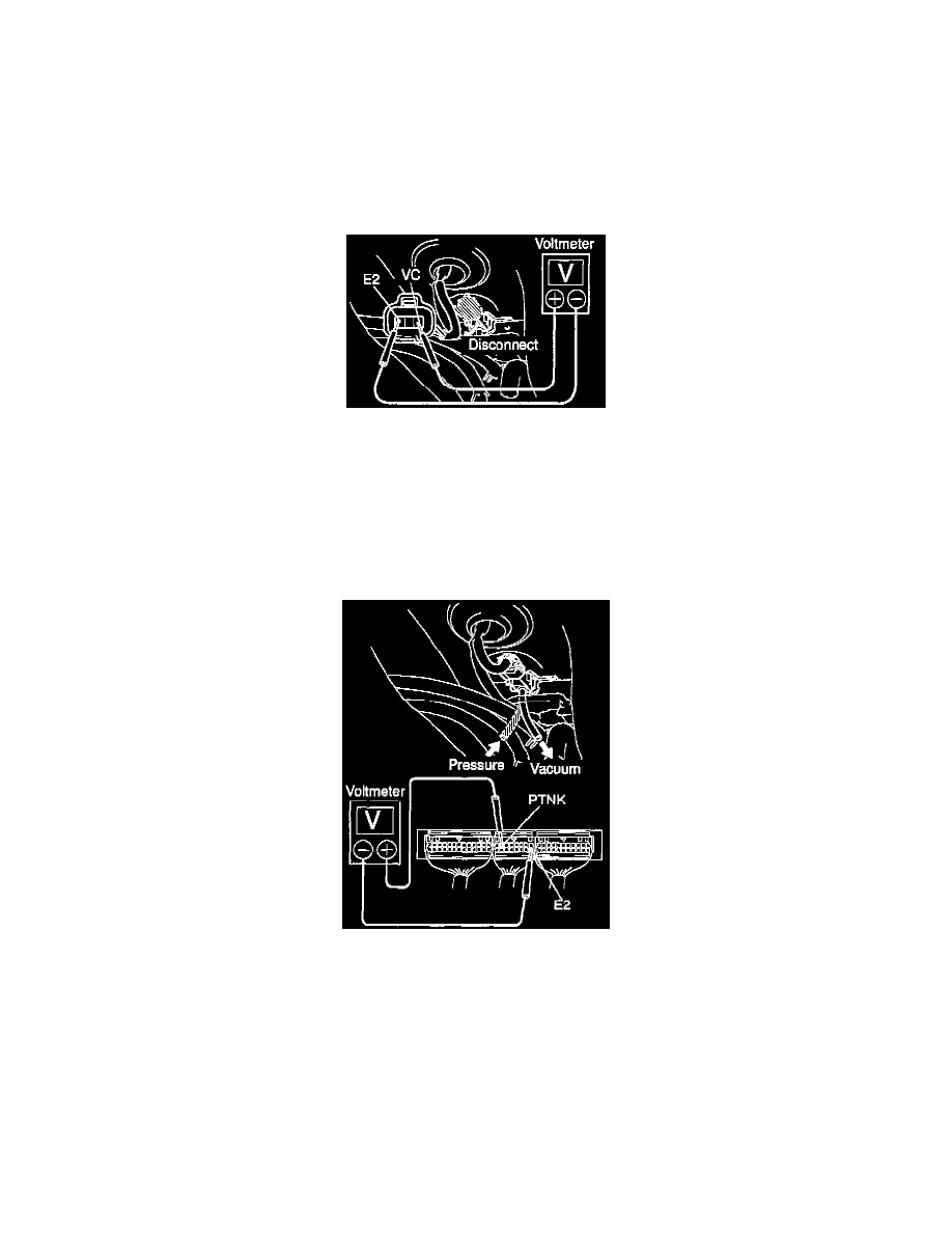
1. INSPECT POWER SOURCE VOLTAGE OF VAPOR PRESSURE SENSOR
(a) Disconnect the vapor pressure sensor connector.
HINT: Near the fuel tank.
(b) Turn the ignition switch ON.
(c) Using a voltmeter, measure the voltage between connector terminals VC and E2 of the wiring harness side.
Voltage: 4.5 - 5.5V
(d) Turn the ignition switch to LOCK.
(e) Reconnect the vapor pressure sensor connector.
2. INSPECT POWER OUTPUT OF VAPOR PRESSURE SENSOR
(a) Turn the ignition switch ON.
(b) Disconnect the vacuum hose from the vapor pressure sensor.
(c) Connect a voltage to terminals PTNK and E2 of the ECM and measure the output voltage under the following connectors:
-
Apply vacuum (2.0 kPa, 15 mmHg, 0.59 in.Hg) to the vapor pressure sensor.
Voltage: 1.3 - 2.1 V
-
Release the vacuum from the vapor pressure sensor
Voltage: 3.0 - 3.6 V
-
Apply pressure (1.5 kPa, 15 gf/sq.cm, 0.22 psi) to the vapor pressure sensor.
Voltage: 4.2 - 4.8 V
(d) Disconnect the vacuum hose to the vapor pressure sensor.