
Corolla Sedan 4-Door L4-1587cc 1.6L DOHC MFI (1997)
3. Disconnect brake lines.
Using Special Service Tool (SST) # 09751-36011, disconnect the brake lines from the Anti-Lock Brake System (ABS) Actuator.
Torque: 15 Nm (11 ft. lbs.)
4. Disconnect No.4 front brake line.
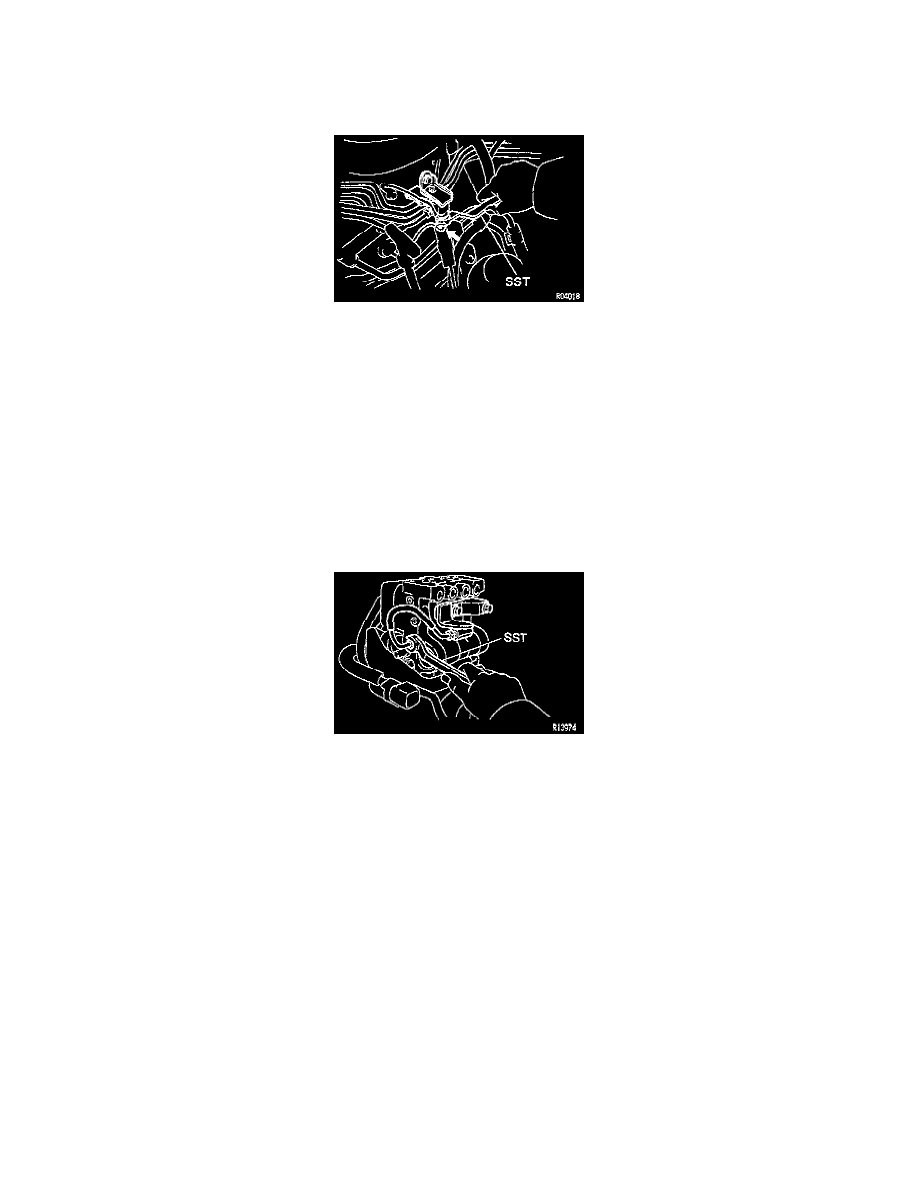
Disconnecting No. 4 Front Brake Line With SST
Using SST, disconnect the No.4 front brake line from the 2-way.
SST 09751-36011
Torque: 15 Nm (11 ft. lbs.)
5. Remove No.2 brake line w/grommet clamp and 2-way.
6. Remove ABS Actuator.
(a) Disconnect the 2 connectors.
(b) Remove the nut, 2 bolts and ABS Actuator assembly.
Torque: 19 Nm (14 ft. lbs.)
(c) Remove the 3 nuts, Actuator No.4 bracket and ABS Actuator from the Actuator bracket assembly.
Torque: 5.4 Nm (48 inch lbs.)
(d) Remove the 3 holders and cushions from the ABS Actuator.
7. If nessary, remove Brake Actuator No.1 line and 2-way.
Disconnecting Brake Actuator No. 1 Line With SST
(a) Using SST, disconnect the brake actuator No.1 line from the ABS Actuator.
SST 09751-36011
Torque: 15 Nm (11 ft. lbs.)
(b) Remove the bolt and 2-way from the ABS Actuator.
Torque: 19 Nm (14 ft. lbs.)
INSTALLATION
Installation is in the reverse order of removal.
-
After installation, fill brake reservoir with brake fluid, bleed brake system. See: Brake Bleeding/Service and Repair
-
Check for leaks.