
Corolla Sedan 4-Door L4-1587cc 1.6L DOHC MFI (1997)
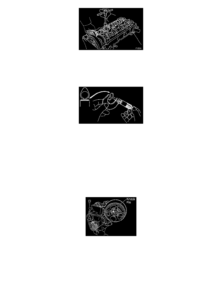
NOTE: If the camshaft is not being lifted out straight and level, reinstall the No.3 bearing cap with the 2 bolts. Than alternately loosen and
remove the bearing cap bolts with the camshaft gear pulled up.
CAUTION: Do not pry on or attempt to force the camshaft with a tool or other object.
2. Remove adjusting shim. Remove the adjusting shim with a small screwdriver.
3. Determine the replacement adjusting shim size by following the formula below as follows:
a. Using a micrometer, measure the thickness of the removed shim.
b. Calculate the thickness of a new shim so that the valve clearance comes with in the specified value.
(1) GT - Thickness of removed shim
(2) A - Measured valve clearance
(3) N - Thickness of new shim
(4) Intake: N = T + (A - 0.20 mm (0.008 inch))
c. Select a new shim with a thickness as close as possible to the calculated value.
NOTE: Shims are available in 16 sizes in increments of 0.05 mm (0.0020 inch), from 2.55 mm (1.0039 inch) to 3.30 mm (0.1299 inch).
4. Install new adjusting shim. Place a new adjusting shim on the valve lifter.
5. Install intake camshaft as follows:
CAUTION: Since the thrust clearance of the camshaft is small, the camshaft must be kept level while it is being installed. If the camshaft is not
kept level, the portion of the cylinder head receiving the shaft thrust may crack or be damaged, causing the camshaft to seize or break. To avoid
this, the following steps should be carried out.
a. Turn the crankshaft pulley, set the exhaust camshaft so the knock pin is slightly above the top of the cylinder head.
b. Apply MP grease to the thrust portion of the camshaft.
c. Engage the intake camshaft gear to the exhaust camshaft gear by matching the assembly installation mark on each gear.
CAUTION: There are also timing marks (for TDC) on each gear. Do not use these marks.
d. Roll down the intake camshaft onto the bearing journals while engaging gears with each other.
NOTE: The above angle allows the No. 1 and No. 3 cylinder cam lobes of the intake camshaft to push their valve lifters evenly.