
Corona L4-2366cc 22R (1982)
Control Module HVAC: Adjustments
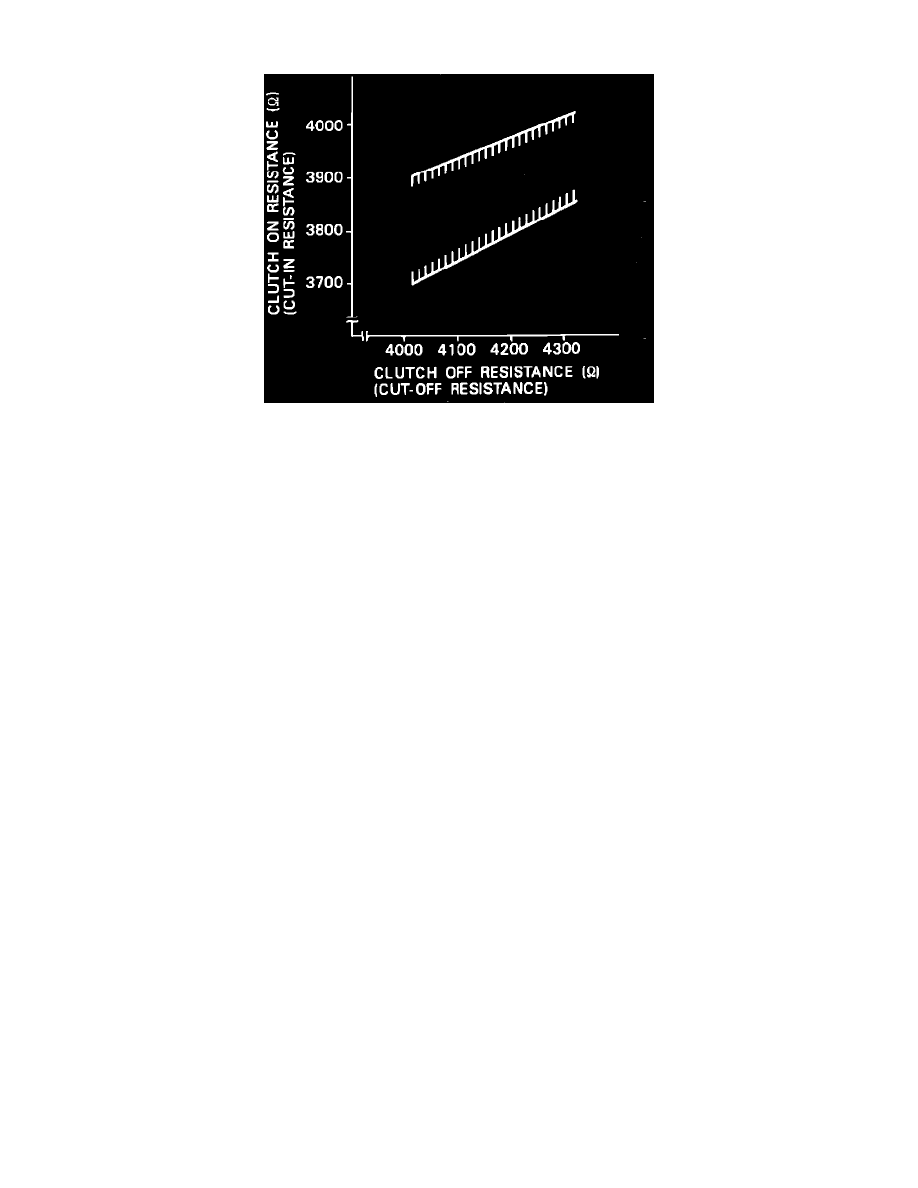
Fig. 14 Idling Stabilizer Amplifier Cut-In/Cut-Off RPM Resistance Graph.
1.
Disconnect electrical connector from thermistor and connect variable resistor.
2.
Operate engine and air conditioner at maximum cooling, air-intake control at RECIRC, air flow control at VENT, temperature control at COOL
and blower control at HI.
3.
Using an ohmmeter, measure resistance of variable resistor at magnetic clutch cut-off and cut-in. Correct cut-off resistance should be 4000 to 4300
ohms. Correct cut-in resistance is indicated in Fig. 14.
4.
If operating point is too high, turn resistor shaft clockwise. If operating point is low turn resistor shaft counterclockwise.