
Paseo Coupe L4-1497cc 1.5L DOHC MFI (1997)
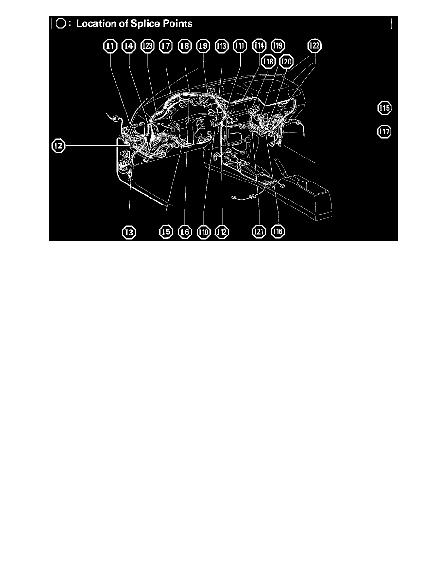
Location Of Splice Points (Fig 34)
System Outline
1. HEATER BLOWER MOTOR OPERATION
Current is applied at all times through the HEATER fuse to TERMINAL 5 of heater Relay.
When the ignition SW is turned ON, current flows through gauge fuse to TERMINAL 3 of the heater Relay --> coil --> TERMINAL 1 -->
TERMINAL 5 of the Blower SW.
* Low Speed Operation
When the blower SW is moved to LO position, the current flows to TERMINAL 1 of blower SW --> TERMINAL 8 --> GROUND, causing
the Heater Relay to ON. This causes the current flowing from the HEATER fuse --> TERMINAL 5 of the Heater Relay --> TERMINAL 4
--> TERMINAL 1 of the blower motor --> TERMINAL 2 --> TERMINAL 1 of the Blower Resistor --> TERMINAL 4 --> GROUND,
causing the blower motor to rotate at low speed.
* Medium Speed Operation (Operation at M 1, M 2)
When the blower SW is moved to M1 position, the current flows to TERMINAL 1 of blower SW --> TERMINAL 8 --> GROUND, and
turned the Heater Relay ON. This causes the current flowing from the Heater fuse --> TERMINAL 5 of the heater Relay --> TERMINAL 4
--> TERMINAL 1 the blower motor --> TERMINAL 2 --> TERMINAL 1 of the blower resistor --> TERMINAL 2 --> TERMINAL 3 of
the blower SW --> TERMINAL 8 --> GROUND. This time, the blower resistance of the blower resistor is less than at low speed, so the
blower motor rotates at medium low speed.
When the blower SW is moved to M2 position, current flowing through the motor flows from TERMINAL 1 of the Blower Resistor -->
TERMINAL 3 --> TERMINAL 2 of the blower SW --> TERMINAL 8 --> GROUND. This time, resistance of the blower resistor is less
than at M1 position, so the blower motor rotates at medium high speed.
* High Speed Operation
When the blower SW is moved to HI position, the current flows to TERMINAL 1 of blower SW --> TERMINAL 8 --> GROUND and turns
the Heater Relay ON.
This causes the current flowing from the Heater fuse to TERMINAL 5 of the Heater Relay --> TERMINAL 4 --> TERMINAL 1 of blower
motor --> TERMINAL 2 --> TERMINAL 6 of the blower SW --> TERMINAL 8 --> GROUND, causing the blower motor to rotate at high
speed.
2. RADIATOR FAN AND CONDENSER FAN OPERATION
When the ignition SW is turned ON, the current flows from the ECU-IG fuse to TERMINAL 2 of the Fan Relay --> TERMINAL 1 -->
TERMINAL 3 of the A/C single pressure SW --> TERMINAL 2 --> TERMINAL 1 of the water temp. SW (Radiator Fan) --> GROUND,
activating the Fan Relay. At this time, current is supplied from RAD FAN fuse to TERMINAL 4 of the Fan Relay. At the same time, current from