
Paseo Coupe L4-1497cc 1.5L DOHC MFI (1997)
1. SHIFT LOCK MECHANISM
With the Ignition SW ON, when a signal that the brake pedal is depressed (stop light SW ON) and a signal that the shift lever is in "P" position is
input to the Shift Lock ECU. The Shift Lock ECU operates and current flows from TERMINAL 2 of the Shift Lock ECU --> the Shift lock
Solenoid --> Solenoid --> TERMINAL 4 of the Shift Lock ECU --> GROUND. This causes the shift lock solenoid to turn ON (plate stopper
disengages) and the shift lever can be shift into other position than the "P" position.
2. KEY INTER LOCK MECHANISM
With the Ignition SW in ON or ACC position, when the shift lever is in "P" position, the current flowing from TERMINAL 3 of the Shift Lock
ECU --> Key Interlock Solenoid is cut off. This causes the key interlock solenoid to turn OFF (lock lever disengages from lock position) and the
Ignition key can be turned from ACC to LOCK position.
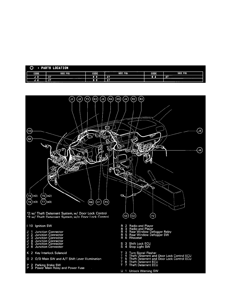
Parts Location
Parts Location
Position Of Parts In Instrument Panel (Part 2 Of 2) (Fig 27)