
Previa Van LE 4WD L4-2438cc 2.4L DOHC SC MFI (1997)
-
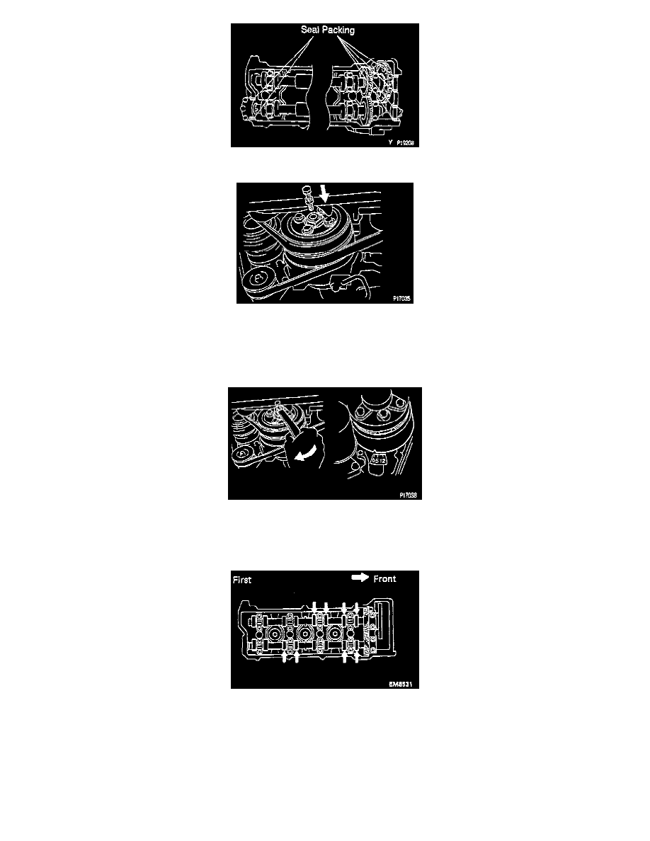
Apply seal packing Part No. 08826-00080 or equivalent to the 6 locations of the cylinder head as shown in the illustration.
3. Install bolt and nut to equipment drive shaft.
INSTALLATION CAUTION: If the service bolt and nut are not removed, the bolt head will hit and damage the cooling fan.
4. Set No.1 cylinder to TDC/compression.
(a) Turn the equipment drive shaft with a wrench to align the timing marks at TDC. Set the groove on the crankshaft pulley to the "0" position.
(b) Check that the valve lifters on the No.1 cylinder are loose and valve lifters on the No.4 are tight. If not, turn the equipment drive shaft 1
complete revolution (360°) and align marks as above.
5. Inspect valve clearance.
(a) Check only the valves indicated in the illustration.
-
Using a thickness gauge, measure the clearance between the valve lifter and camshaft.
-
Record the out-of-specification valve clearance measurements. They will be used later to determine the required replacement adjusting
shim.
Valve clearance (Cold):
Intake: 0.15 - 0.25 mm (0.006 - 0.010 inch)
Exhaust: 0.25 - 0.35 mm (0.010 - 0.014 inch)
(b) Turn the equipment drive shaft one revolution (360°) and align the marks as above.