
Previa Van LE 4WD L4-2438cc 2.4L DOHC SC MFI (1997)
0.3-0.4 K Ohms (80°C, 176°F)
S13 STOP LIGHT SW
1-3:
Closed with the brake pedal depressed
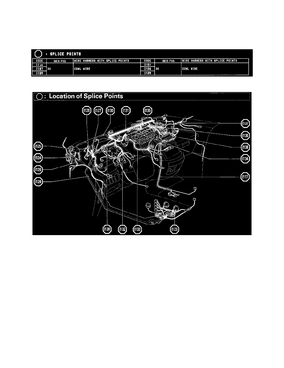
Splice Points
Splice Points
Location Of Splice Points (Fig 30)
System Outline
Previous automatic transmissions have selected each gear shift using mechanically controlled throttle hydraulic pressure, governor hydraulic pressure
and lock-up hydraulic pressure. The electronically controlled transmission, however, electronically controls the line pressure and lock-up pressure etc.,
through the solenoid valve. Engine control module control of the solenoid valve based on the input signals from each sensor makes smooth driving
possible by shift selection for each gear which is most appropriate to the driving conditions at that time.
1. GEAR SHIFT OPERATION
During driving, the engine control module selects the shift for each gear which is most appropriate to the driving conditions, based on input signals
from the engine coolant temp. sensor to TERMINAL THW of the engine control module, and also the input signals to TERMINAL SP2 of the
engine control module from the vehicle speed sensor devoted to the electronically controlled transmission. Current is then output to the
electronically controlled transmission solenoids. When shifting to 1st speed, current flows from TERMINAL S1 of the engine control module -->
TERMINAL 1 of the electronically controlled transmission solenoids --> GROUND, and continuity to the No.1 solenoid causes the shift.
For 2nd speed, current flows from TERMINAL S1 of the engine control module --> TERMINAL 1 of the electronically controlled transmission
solenoids --> GROUND, and from TERMINAL S2 of the engine control module --> TERMINAL 2 of the electronically controlled transmission
solenoid --> GROUND, and continuity to solenoids No.1 and No.2 causes the shift.
For 3rd speed, there is no continuity to No.1 solenoid, only to No.2. causing the shift.