
Starlet L4-1290cc 4KE (1983)
Radiator Cooling Fan Motor: Service and Repair
FAN MOTOR, REPLACE
1.
Disconnect battery ground cable.
2.
Disconnect electrical connector from fan motor.
3.
Remove front grille and cooling fan assembly.
4.
Remove attaching nut, then separate fan blade spacer from motor.
5.
Remove bushings and attaching screws, then separate fan motor from shroud.
6.
Reverse procedure to assemble and install.
TROUBLESHOOTING
1.
If coolant temperature is low (below 196°F), proceed as follows:
a. Turn ignition switch on and ensure cooling fan is not operating.
b. If fan is operating, a faulty fan relay and/or temperature switch is indicated. Check for separated electrical connectors or severed wire
between relay and temperature switch.
c. Disconnect temperature switch wire, then check that fan rotates.
d. If fan does not rotate, check fan relay, fan motor, ignition relay and fuse. Check for short circuit between fan relay and temperature switch.
e. Connect temperature switch wire.
2.
If coolant temperature is high (above 203°F), proceed as follows:
a. Raise engine temperature to above 203°F, then check that fan rotates.
b. If fan does not rotate, replace temperature switch.
COMPONENT INSPECTION
1.
Using a suitable ohmmeter, check temperature switch, located on water inlet housing, as follows:
a. Check for no continuity when water temperature is above 203°F. No continuity should exist.
b. Check for continuity when water temperature is below 203°F. Continuity should be present.
c. If continuity checks are not as specified, replace switch.
2.
Check ignition switch relay in left kick panel as follows:
Fig. 6 Checking ignition switch relay. Starlet, Tercel Wagon & 1984-86 Tercel Sedan
a. Using a suitable ohmmeter, measure resistance between terminals 1 and 2, Fig. 6. Resistance should be 50-80 ohms.
b. Connect a 12 volt source across terminals 1 and 2, then check that continuity exists between terminals 3 and 4, using a suitable ohmmeter.
c. If ignition relay does not perform as indicated in steps a and b, replace relay.
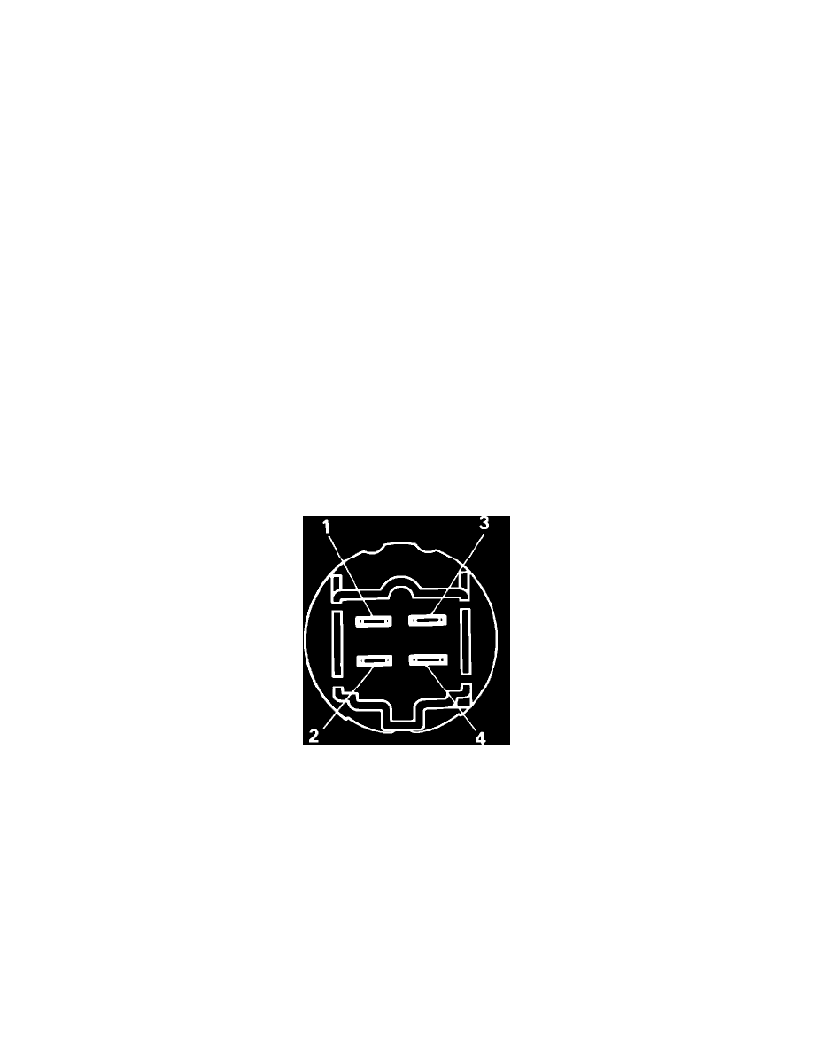
3.
Inspect cooling fan motor relay, located in left kick panel, as follows:
a. Using a suitable ohmmeter, measure resistance between terminals 1 and 2, Fig. 1. Resistance should be 50-80 ohms.
b. Connect a 12 volt source between terminals 1 and 2, then using a suitable ohmmeter, check for continuity between terminals 3 and 4.
c. If fan motor relay does not perform as indicated in steps a and b, replace relay.
4.
Connect a suitable ammeter and battery to fan motor connector, Fig. 2. Ensure motor rotates smoothly and current is 4.2-5.4 amps.