
Supra L6-2997cc 3.0L DOHC MFI (1998)
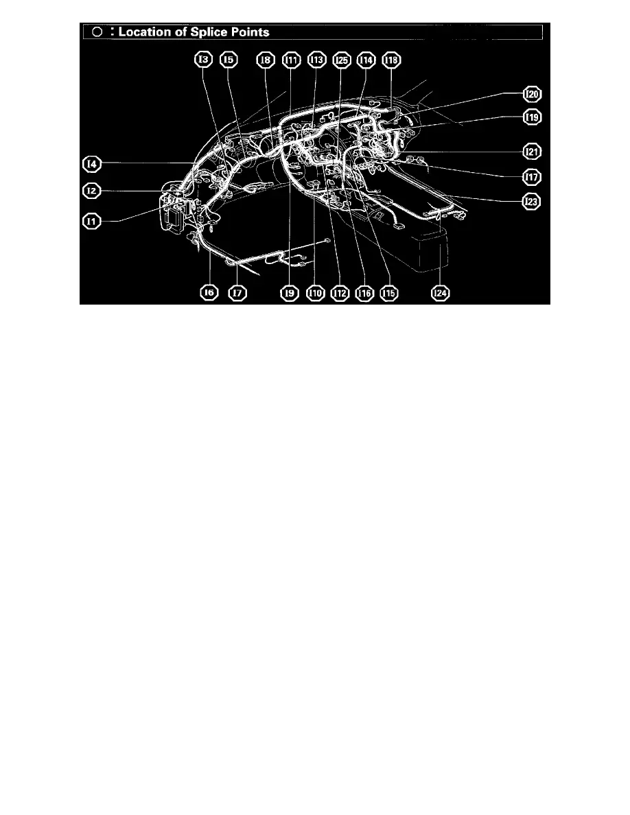
Location Of Splice Points (Fig 38)
System Outline
This system electrically controls the line pressure, throttle pressure, lock-up pressure and accumulator pressure etc. through the solenoid valve. The
electronically controlled transmission is a system which precisely controls gear shift timing and lock-up timing in response to the vehicle's driving
conditions and the engine operating conditions detected by various sensors, making smooth driving possible by shift selection for each gear which is the
most appropriate to the driving conditions at that time, and controls the engine torque during shifting to achieve optimum shift feeling.
1. GEAR SHIFT OPERATION
When driving, the engine warm up condition is input as a signal to TERMINAL (B) 14 of the engine control module from the engine coolant
temp. sensor and the vehicle speed signal from the vehicle speed sensor No. 2 is input to TERMINAL (C) 5 of the engine control module. At the
same time, the throttle valve opening signal from the throttle position sensor is input to TERMINAL (B) 23 of the engine control module as
throttle angle signal.
Based on these signals, the engine control module selects the best shift position for driving conditions and sends current to the electronically
controlled transmission solenoids.
When shifting to 1st speed, the current flows from TERMINAL (C) 1 of the engine control module to TERMINAL 5 of the electronically
controlled transmission solenoid to GROUND and continuity to No. 1 solenoid causes the shift (No. 2 solenoid does not have continuity at this
time).
For 2nd speed, the current flows simultaneously from TERMINAL (C) 2 of the engine control module to TERMINAL 10 of electronically
controlled transmission solenoid to GROUND, and from TERMINAL (C) 1 of the engine control module to TERMINAL 5 of the electronically
controlled transmission solenoid to GROUND, and continuity to No. 1 and No. 2 solenoids causes the shift.
For 3rd speed, there is no continuity to No. 1 solenoid, only to No. 2 solenoid, causing the shift.
Shifting into the 4th speed (Overdrive) occurs when no current flows to No. 1 and No. 2 solenoids.
2. LOCK-UP OPERATION
When the engine control module judges from each signal that lock-up operation conditions have been met, current flows from TERMINAL (C) 7
of the engine control module to TERMINAL 4 of the electronically controlled transmission solenoid to TERMINAL 9 to TERMINAL (C) 13
of the engine control module to GROUND, causing continuity to the lock-up solenoid and causing lock-up operation.
3. STOP LIGHT SW CIRCUIT
If the brake pedal is depressed (Stop light SW on) when driving in lock-up condition, a signal is input to TERMINAL (D) 6 of the engine control
module. The engine control module operates and cuts the current to the solenoid to release lock-up.
4. OVERDRIVE CIRCUIT
* O/D main SW on