
Supra L6-2997cc 3.0L DOHC MFI (1998)
E 9 (A), E10 (B), E12 (C), E13 (D), E14 (E), E15 (F) ENGINE CONTROL MODULE
BATT-E1:
Always 9-14 Volts
+BM-E1:
9-14 Volts with the ignition SW ON
IGSW-E1:
9-14 Volts with the ignition SW ON
+B-E1:
9-14 Volts with the ignition SW ON
VTA1-E1:
0.4-1.0 Volts with the ignition SW ON and the throttle valve fully closed
3.2-4.8 Volts with the ignition SW ON and the throttle valve fully open
VTA2-E2:
1-2.9 Volts with the throttle valve fully closed
4.6-5 Volts with the throttle valve fully open
STA-E1:
6-14 Volts with the engine cranking
MREL-E1:
9-14 Volts with the ignition SW ON
VC-E1:
4.5-5.5 Volts with the ignition SW ON
L-E1:
7.5-14 Volts with the shift lever at L position
2-E1:
7.5-14 Volts with the shift lever at 2 position
V11 VEHICLE SPEED SENSOR NO. 2 (ELECTRONICALLY CONTROLLED TRANSMISSION)
1-2:
Approx. 620 Ohms
E 8 ELECTRONICALLY CONTROLLED TRANSMISSION PATTERN SELECT SW
4-3:
Closed with electronically controlled transmission pattern select SW at MANUAL position
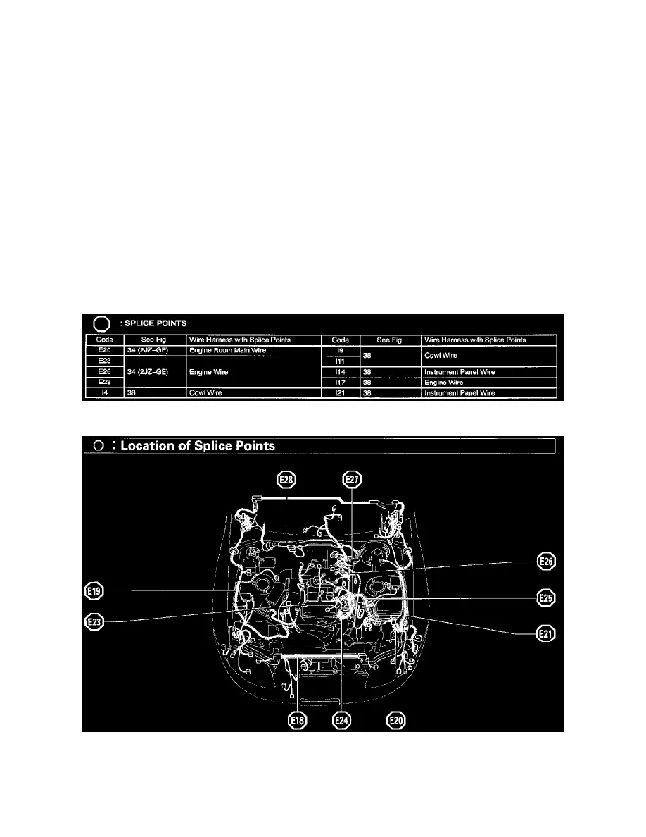
Splice Points
Splice Points
Location Of Splice Points (Fig 34)