
Supra Liftback L6-2997cc 3.0L DOHC MFI Twin-Turbo (1997)
Fuel Pump Control Unit: Testing and Inspection
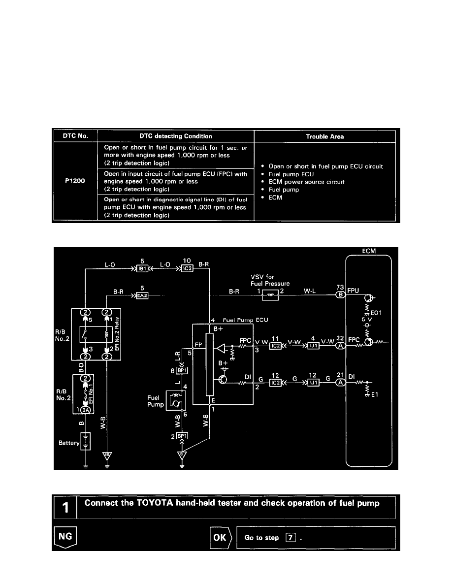
DTC P1200 Fuel Pump Relay/ECU Circuit Malfunction
CIRCUIT DESCRIPTION
The fuel pump speed is controlled at 2 steps (high speed, low speed) by the condition of the engine (starting, light load, heavy load), when the
engine starts (STA ON), the ECM sends a Hi signal (about 5 V) to the fuel pump ECU (FPC terminal).
The fuel pump ECU then outputs Hi voltage (battery positive voltage) to the fuel pump so that the fuel pump operates at high speed.
After the engine starts, during idling or light loads, the ECM outputs a Low signal (about 2.5 V) to the fuel pump ECU, the fuel pump ECU
outputs Low voltage (about 9 V) to the fuel pump and causes the fuel pump to operate at low speed.
If the intake air volume increases (high engine load), the ECM sends a Hi signal to the fuel pump ECU and causes the fuel pump to operate at high
speed.
DETECTING CONDITION
WIRING DIAGRAM