
Supra Liftback L6-2997cc 3.0L DOHC MFI Twin-Turbo (1997)
1-5:
Approx. 3.8 Ohms
E 3 ENGINE COOLANT TEMP. SENSOR
1-2:
10-20 K Ohms (-20° C, -4° F)
4-7 K Ohms (0° C, 32° F)
2-3 K Ohms (20° C, 68° F)
0.9-1.3 K Ohms (40° C, 104° F)
0.4-0.7 K Ohms (60° C, 140°F)
0.2-0.4 K Ohms (80°C, 176° F)
E 9-B, E10-A ENGINE CONTROL MODULE
BATT-E1:
Always 9-14 Volts
IGSW-E1:
9-14 Volts with the ignition SW ON
+B-E1:
9-14 Volts with the ignition SW ON
IDL1-E1:
0-1.5 Volts with the ignition SW ON and the throttle valve fully closed
9-14 Volts with the ignition SW ON and the throttle valve fully open
VTA1-E1:
0.3-0.8 Volts with the ignition SW ON and the throttle valve fully closed
3.2-4.9 Volts with the ignition SW ON and the throttle valve fully open
STA-E1:
6-14 Volts with the engine cranking
M-REL-E1: 9-14 Volts with the ignition SW ON
VCC-E1:
4.5-5.5 Volts with the ignition SW ON
L-E1:
Approx. 7.5-14 Volts with the shift lever at "L" position
2-E1:
Approx. 7.5-14 Volts with the shift lever at "2" position
R-E1:
Approx. 7.5-14 Volts with the shift lever at "R" position
O 1 O/D DIRECT CLUTCH SPEED SENSOR
1-2:
Approx. 620 Ohms
V11 VEHICLE SPEED SENSOR NO.2 (ELECTRONICALLY CONTROLLED TRANSMISSION)
1-2:
Approx. 620 Ohms
E 8 ELECTRONICALLY CONTROLLED TRANSMISSION PATTERN SELECT SW
4-3:
Closed with E1ectronically controlled transmission pattern select SW at MANUAL position
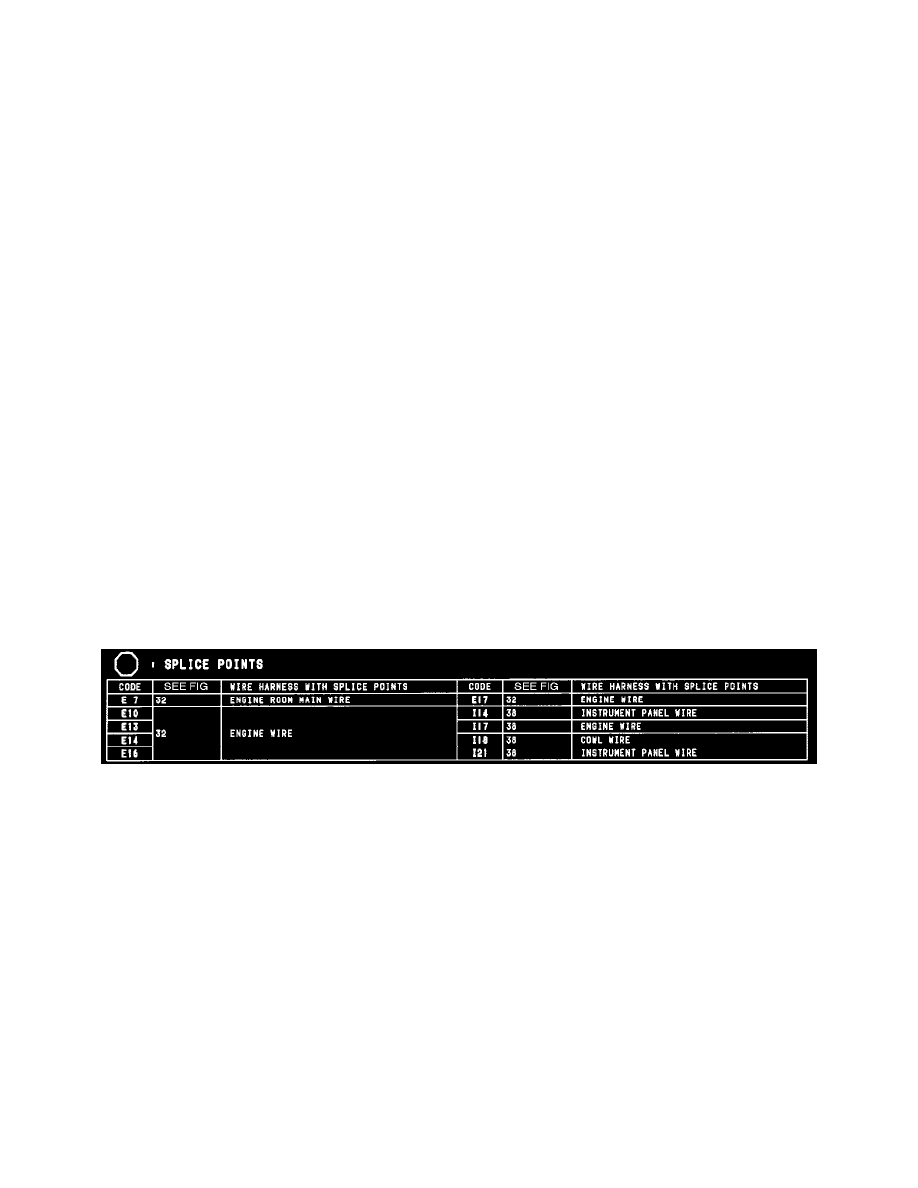
Splice Points
Splice Points