
Supra Liftback L6-2997cc 3.0L DOHC MFI Twin-Turbo (1997)
Engine Control Module: Testing and Inspection
Control Module Pinout Values
STANDARD VALUES OF ECM TERMINALS
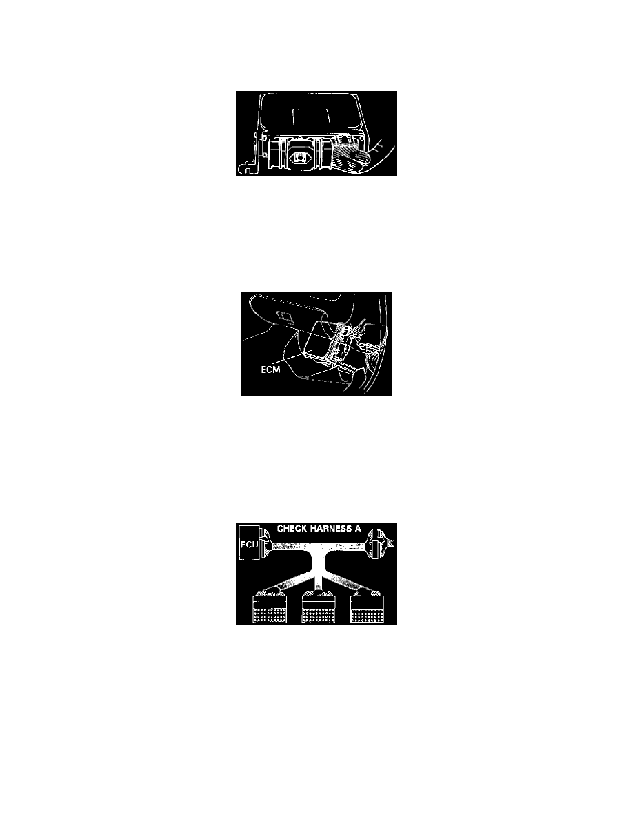
Connectors of the ECM are water-proof and are the bolt type. For water proof type connectors, in order to measure the voltage of ECM terminals and the
resistance of connected parts, connect the inspection check harness between the ECM and vehicle wire harness, then perform the inspection.
The inspection method of inserting a tester probe from the other side of connector noticeably reduces the water-proof ability.
Disconnect the connector by fully loosening the bolt.
PREPARATION
1. Turn the ignition switch to LOCK position.
2. Turn up the passenger side floor mat.
3. Remove the ECM protector.
4. Disconnect the connectors from the ECM.
After completely loosening the bolt, the 2 parts of connector can be separated.
NOTICE:
-
Do not pull the wire harness when disconnecting the connector.
-
When disconnecting the connector, the ECM's backup power source is cut off, so the DTC, etc. recorded in the ECM memory are cancelled.
-
Never insert a tester probe or male terminal used for inspection purposes into the female terminal of the vehicle wire harness. Otherwise, the
female terminal may be widened, which can result in faulty connection.
5. Connect the Check Harness A between ECM and connector of vehicle wire harness. SST 09990-01000
HINT: The arrangement of the DLC1 terminals are the same as those of the ECM.
6. Disconnect the Check Harness A.
7. Reconnect the connectors to the ECM.