
Supra Liftback L6-2997cc 3.0L DOHC MFI Twin-Turbo (1997)
Drive/Propeller Shaft: Service and Repair
Installation
1. Install propeller shaft.
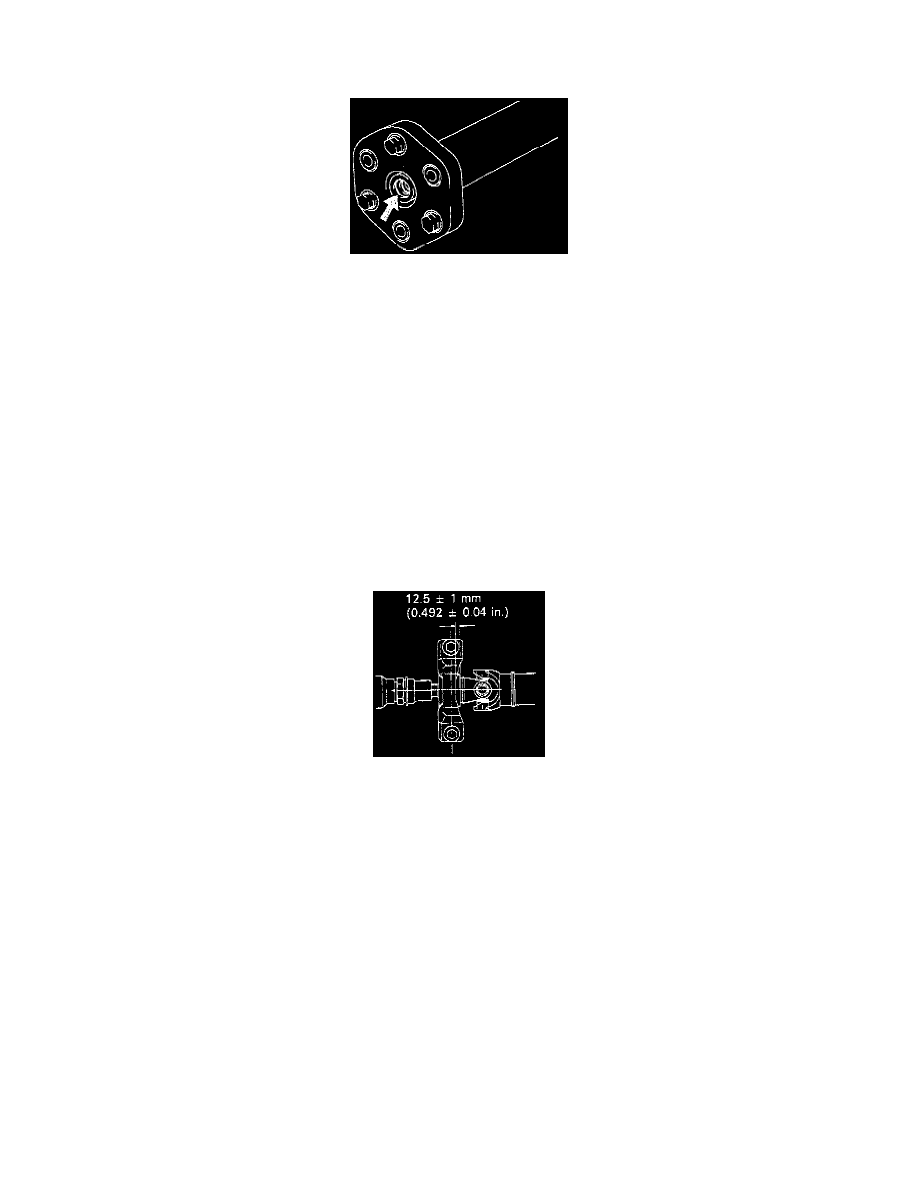
a. Apply Molybdenum disulfide lithium base, NLGI No.1 or No.2 grease to the flexible coupling centering bushings.
b. Align the matchmarks on the flanges and connect the flanges with the 4 nuts and washers.
c. Torque the 4 nuts.
Torque to: 56 N.m (41 ft. lbs.)
d. Insert the propeller shaft from the vehicle's rear and connect the transmission and differential.
NOTICE: Support the center support bearing by hand so that the transmission and intermediate shaft, and propeller shaft and differential,
remain in a straight line.
e. Temporarily install the 2 center support bearing set bolts with the adjusting washers.
NOTE: Use the adjusting washers which were removed.
f.
Align the matchmarks and install the propeller shaft on the differential with the 3 bolts, washers and nuts. (Bolts should be inserted from the
propeller shaft side.)
Torque to: 79 N.m (58 ft. lbs.)
g. Torque the 2 center support bearing set bolts.
Torque to: 49 N.m (36 ft. lbs.)
HINT: Adjust the center support bearing to keep the dimension, as shown with the vehicle in the unladen condition. Under the same
condition, check if the center line of the center support bearing is at right angles to the shaft axial direction.
NOTICE: If using a new propeller shaft:
-
w/ Phasemarks: Install the propeller shaft phasemarks and differential phasemarks so that their respective alignment phasemarks match.
If the propeller shaft phasemarks and differential phasemarks do not align, install the propeller shaft and differential alignment phasemarks
as close together as possible.
-
w/O Phasemarks: Install the propeller shaft.
h. Using Special Service Tool (SST) 09922-10010, or equivalent, torque the adjusting nut.
Torque to: 50 N.m (37 ft. lbs.)
NOTE: Use torque wrench with a fulcrum length 34.5 cm (13.6 inch)
2. Inspect propeller shaft joint angle.
NOTICE: The joint angle should be checked when the propeller shaft is removed and installed.
3. Install crossmember brace.
-
Normal Roof: Install the center floor crossmember brace and torque the 4 bolts.
Torque to: 13 N.m (8 ft. lbs.)
-
Sport Roof: Install the center floor crossmember brace and torque the 6 bolts.