
Supra Sport Roof L6-2997cc 3.0L DOHC MFI (1998)
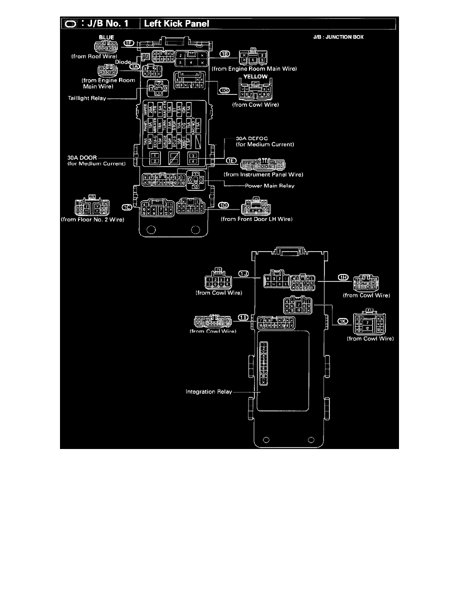
Locations-J/B No.1, Left Kick Panel (Fig 20)
System Outline
When the ignition SW is turned to ACC position the current from the CIG fuse flows to TERMINAL 5 of the shift lock ECU, in the ON position, the
current from the ECU-IG fuse flows to TERMINAL 1 of the ECU.
1. SHIFT LOCK MECHANISM
With the ignition SW ON, when a signal that the brake pedal is depressed (Stop light 5W on) and a signal that the shift lever is put in P position
(Continuity between P1 and P of the shift lock control SW) is input to the ECU, the ECU operates and current flows from TERMINAL 1 of the
ECU to TERMINAL SLS+ of the shift lock solenoid to solenoid to TERMINAL SLS to TERMINAL 4 of the ECU to GROUND. This causes
the shift lock solenoid to turn ON (Plate stopper disengages) and the shift lever can shift into position other than the P.
2. KEY INTERLOCK MECHANISM