
Tacoma Extra Cab 4WD L4-2693cc 2.7L DOHC MFI (1997)
Mass Air Flow Meter: Description and Operation
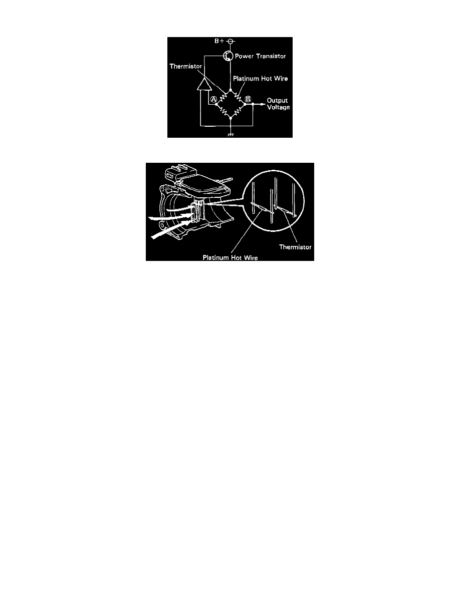
Circuit Schematic
Sensor Cut-Away
CIRCUIT DESCRIPTION
The mass air flow meter uses a platinum hot wire. The hot wire air flow meter consists of a platinum hot wire, thermistor and a control circuit
installed in a plastic housing. The hot wire air flow meter works on the principle that the hot wire and thermistor located in the intake air bypass of
the housing detect any changes in the intake air temperature.
The hot wire is maintained at the set temperature by controlling the current flow through the hot wire. This current flow is then measured as the
output voltage of the air flow meter.
The circuit is constructed so that the platinum hot wire and thermistor provide a bridge circuit, with the power transistor controlled so that the
potential of (A) and (B) remains equal to maintain the set temperature.