Cylinder Head, Remove and Install Notice: Operation is described for C 20 NE. For all other engines proceed analogously.
 Important! Important! Only remove cylinder head with engine cold (room temperature). Fuel escapes - observe safety and local regulations. Fuel system is under pressure. Remove fuel pump relay - see operation "Fuel Pump Relay, Remove and Install". Start engine at least 5 sec. - fuel pressure reduction.
 Remove, Disconnect Remove, Disconnect Remove air intake hose. Detach lower coolant hose (1) from coolant pipe - collect coolant. Detach brake servo vacuum line (2) and ground connections (3) from intake manifold. Disconnect multiple plug (4), detach wiring harness plug (5) from idle speed adjuster. | 
|
Remove, Disconnect Detach engine vent hoses (1) from throttle body, detach accelerator Bowden cable from throttle body. Detach ground connections (2) from camshaft housing. | 
|
Remove, Disconnect Disconnect wiring harness plug (1) for crankshaft pulse pick-up. Detach wiring harness plug (2) from controlled canister purge valve. Detach vacuum hose from controlled canister purge valve. | 
|
Remove, Disconnect Detach wiring harness plug (1) from throttle valve potentiometer, wiring harness plug (2) from coolant temperature sensor. Detach wiring harness plug from coolant temperature sender. Detach fuel lines - before removal, mark allocation and close off with spring clamps. Detach fuel lines bracket from intake manifold. Detach coolant hose (3) from throttle body. Detach coolant hoses from thermostat housing. Detach retaining clip (4) from injectors, 1st and 4th cylinders. Remove plug strip from injectors upwards. Insert safety clamp in plug strip. Lay complete wiring harness aside - note cable routing. Detach ignition cable from high voltage distributor. | 
|
Remove, Disconnect Engines up to MY '93: detach V-belt or ribbed V-belt from alternator. Detach alternator shackle from intake manifold. Loosen lower alternator fastening bolt - swing alternator to rear. In engines from MY '93: mark direction of motion of the ribbed V-belt. Remove tension from ribbed V-belt in the clockwise direction by means of ribbed V-belt tension roller and KM-913-A and remove ribbed V-belt. Loosen fastening bolts (1) and (2). Remove fastening bolts (3) and (4) from generator. Loosen lower generator fastening bolt - pivot generator rearwards. Detach exhaust pipe from exhaust manifold. Remove toothed belt cover - see operation "Front Toothed Belt Cover, Remove and Install (1.6 / 1.8 Ltr. Engines and 16 LZ2)". | 
|
 Adjust Adjust Before removing the toothed belt - at the fastening bolt of the ribbed toothed belt pulley, move crankshaft in the direction of rotation of the engine 60 ° (Dimension I) before TDC mark. For 1.4 / 1.6 ltr. engine except 16 LZ2: move toothed belt tension roller upwards against the spring force until the holes are aligned and fix toothed belt tension roller with suitable mandrel (1). For 1.8 / 2.0 ltr. engine until MY '93: release fastening bolt of the coolant pump and rotate coolant pump anticlockwise with KM-637. For 1.8 / 2.0 ltr. engine from MY '93 and 16 LZ2: release fastening bolt of the toothed belt tension roller and rotate adjustment eccentric in the direction of the arrow (in the clockwise direction) until the pointer (2) is just before the left-hand stop.
Remove, Disconnect Mark running direction of the toothed belt. Remove toothed belt from camshaft sprocket. Detach camshaft housing cover from camshaft housing, detach camshaft pulley from camshaft - counterhold on hex of camshaft. Remove fastening bolts for rear toothed belt cover from camshaft housing. | 
|
Remove, Disconnect Loosen cylinder head bolts in order shown in a spiral pattern from outside inwards (first 1/4, then 1/2 turn). Remove camshaft housing from cylinder head. Remove cam followers, thrust pieces and hydraulic valve lifters - note allocations. Remove cylinder head from cylinder block.
 Clean Clean Sealing surfaces, bores and threads of cylinder head bolts.
 Inspect Inspect Check cylinder head and cylinder block for plane surface - see operations "Cylinder Head, Check for Plane Surface" and "Cylinder Block, Check for Plane Surface".
 Install, Connect Install, Connect Install cylinder head gasket - mark "OBEN/TOP" on top and towards timing side of engine. | 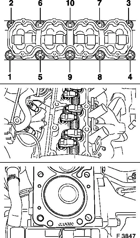
|
Install, Connect Place cylinder head on cylinder block. Insert hydraulic valve lifters, thrust pieces and rocker arms with MoS 2 -sliding paste (grey) - note order. Apply a run of surface sealing (green) to the sealing surface of the cylinder head. Camshaft housing on cylinder head. Attach cylinder head and camshaft housing to cylinder block with new cylinder head bolts. Tighten cylinder head bolts in order shown - use torque wrench and KM-470-B.
|
Engine |
Torque |
Additional angle |
|
1.4 / 1.6 ltr. except 16 LZ2 |
25 Nm/26 lbf. ft. |
60 ° + 60 ° + 60 ° 1) |
|
1.8 / 2.0 ltr. and 16 LZ2 |
25 Nm/26 lbf. ft. |
90 ° + 90 ° + 90 ° 1) |
1) Retightening not required. | 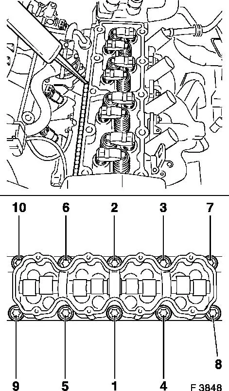
|
Install, Connect Install rear toothed belt cover on camshaft housing. 1) : 1.4 / 1.6 ltr. engine except 16 LZ2 - tightening torque 6 Nm. 1.8 / 2.0 ltr. engine and 16 LZ2 - tightening torque 6 Nm. Attach camshaft pulley to camshaft - 45 Nm/33 lbf. ft. Counterhold on hex of camshaft. Attach camshaft housing cover to housing - 8 Nm/6 lbf. ft. Attach exhaust pipe to exhaust manifold with new gasket - 25 Nm/18 lbf. ft. Install toothed belt - see operation "Toothed Belt, Remove and Install (1.4 / 1.6 Ltr. Engines except 16 LZ2)", "Toothed Belt, Remove and Install (1.8 / 2.0 Ltr. Engines up to MY '93)" or "Toothed Belt, Remove and Install (1.8 / 2.0 Ltr. Engines as of MY '93 and 16 LZ2)". For engines from MY '93: install fastening bolts, support and strap on induction manifold and generator - tightening torque 18 Nm . Tighten lower generator fastening bolt - tightening torque 35 Nm. Place ribbed V-belt in position - tension ribbed V-belt by means of ribbed V-belt tension roller and KM-913-A. Note direction of motion of the ribbed V-belt. For engines to MY '93: install V-belts or ribbed V-belts - see operation "V-belt, Remove and Install" or operation "Ribbed V-belt, Remove and Install ". Attach ignition cable to high voltage distributor.
1) Recut thread and insert fastening bolts with locking agent (red).
Install, Connect Attach coolant hose to throttle body. Attach coolant hoses to thermostat housing. Attach fuel lines bracket. Attach fuel lines - note allocations. Connect plug strip to injectors. Connect wiring harness plugs to coolant temperature sensor, throttle valve potentiometer, coolant temperature sender, crankshaft pulse pick-up and controlled canister purge valve. Attach vacuum hose to controlled canister purge valve. Attach ground connections to intake manifold and camshaft housing. Attach accelerator Bowden cable and engine vent hoses to throttle body. Connect wiring harness plug to idle speed adjuster, connect multiple plug. Attach brake servo vacuum line to intake manifold - 20 Nm/15 lbf. ft. Attach lower coolant hose to coolant pipe. Install air intake hose. Install fuel pump relay - see operation "Fuel Pump Relay, Remove and Install". Cooling system - see operations "Cooling System, Top Up and Bleed" and "Cooling System, Check for Leaks".
|
