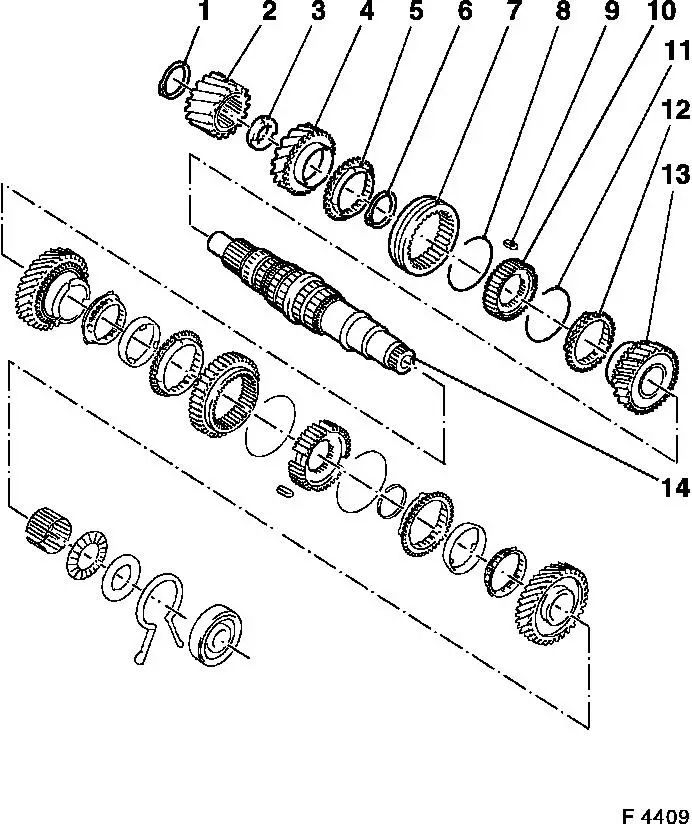
Main Shaft, Disassemble and Assemble F 10/F 13 Illustration
|
1 |
Retaining ring |
|
2 |
Drive gear (driving) |
|
3 |
Spacer washer |
|
4 |
4th gear |
|
5 |
4th gear synchroniser ring |
|
6 |
Retaining ring |
|
7 |
3rd/4th gear shift sleeve |
|
8 |
Synchroniser spring |
|
9 |
Sliding block |
|
10 |
Synchromesh body |
|
11 |
Synchroniser spring |
|
12 |
3rd gear synchroniser ring |
|
13 |
3rd gear |
|
14 |
Main shaft |
| 
|
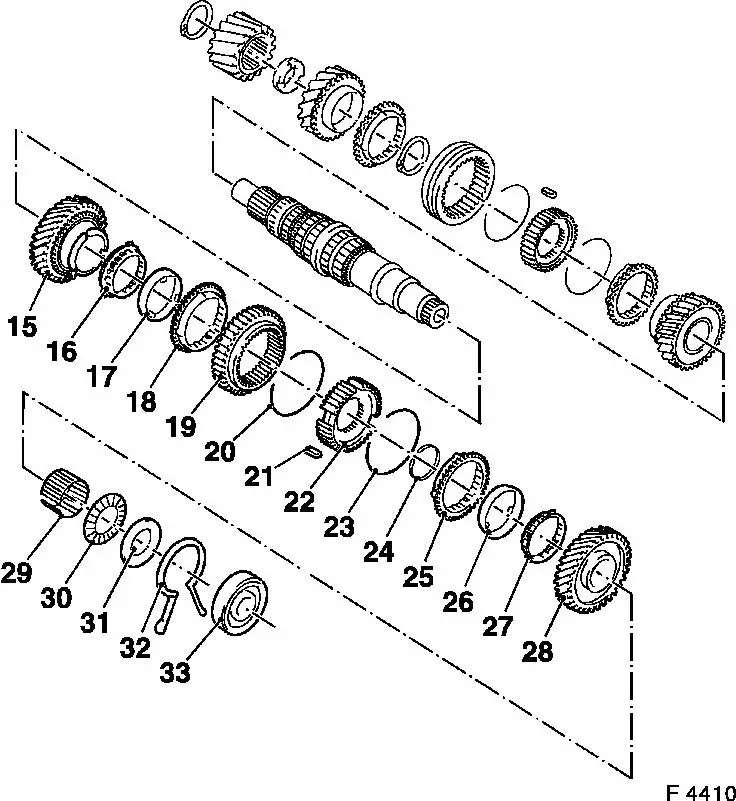
Illustration: Main Shaft F 10/F 13 (Continued)
|
15 |
2nd gear |
|
16 |
Inner synchroniser ring |
|
17 |
Intermediate ring |
|
18 |
Outer synchroniser ring |
|
19 |
1st/2nd gear shift sleeve |
|
20 |
Synchroniser spring |
|
21 |
Sliding block |
|
22 |
Synchromesh body |
|
23 |
Synchroniser spring |
|
24 |
Retaining ring |
|
25 |
Outer synchroniser ring |
|
26 |
Intermediate ring |
|
27 |
Inner synchroniser ring |
|
28 |
1st gear |
|
29 |
1st gear needle bearing |
|
30 |
Axial needle bearing |
|
31 |
Thrust washer |
|
32 |
Retaining ring |
|
33 |
Ball bearing |
| 
|
 Remove, Disconnect Remove, Disconnect Remove end shield - see operation "Gasket for End Shield, Replace". Disassemble end shield - see operation "End Shield, Disassemble and Assemble - F 10/F 13/F 18/F 18+/F 20". Notice: If the gears are damaged, always also replace the gear cluster.
Remove, Disconnect | 
|
Press off ball bearing, retaining ring (long leg), spacer washer, axial needle bearing and 1st gear using appropriate drift. Remove needle bearing for 1st gear from main shaft. Remove 3 synchroniser rings (1st gear), selectors and sliders. Retaining ring for 1st/2nd gear synchromesh body. Press off 1st/2nd gear synchromesh body, 3 synchroniser rings (2nd gear) and 2nd gear using appropriate drift for KM-307-B. Retaining ring in front of drive gear (driving) from main shaft. Press off drive gear (driving) from main shaft - KM-307-B and appropriate drift.
 Important! Important! Always replace drive gears (driving and driven) in pairs. | 
|
Remove, Disconnect Place KM-479-A in groove of 4th gear. Press off spacer washer and 4th gear. | 
|
Remove synchroniser ring (4th gear), shift sleeve and sliders. Retaining ring for 3rd/4th gear synchromesh body from main shaft. Press off 3rd/4th gear synchromesh body and 3rd gear with suitable drift. | 
|
 Clean Clean Clean all parts.
 Inspect Inspect Immerse all parts in transmission fluid before assembly. Check removed parts for damage and wear.
Important! Lubricate all bearing bore holes and seating surfaces with transmission fluid before installation. For all operations requiring heating of transmission parts, check temperature with thermocolour pencils or suitable temperature gauge.
All transmissions have 3 cone synchromesh for 1st/2nd gear:
2 Inner synchroniser rings
4 Outer synchroniser ring
8 Synchromesh body (carrier)
| 
|
 Assemble Assemble Synchromesh body for 1st/2nd gear and 3rd/4th gear. Insert synchroniser springs in slider with their hooks facing in different directions so that free end of spring protrudes from synchromesh body. Insert slider in flat middle tooth of shift sleeve. | 
|
 Install, Connect Install, Connect Push 3rd gear onto main shaft from drive gear side so that cone points towards the drive gear. Place synchroniser ring onto 3rd gear cone. Heat 3rd/4th gear synchromesh body assembly to 100 ° C and press onto transmission shaft, KM-277. New retaining ring in front of 3rd/4th gear synchromesh body. | 
|
Push synchroniser ring and gear wheel 4. gear onto transmission shaft. Warm clearance plate and drive gear (driven) to 100 ° C. Place clearance plate on transmission shaft so that slots face towards gear wheel 4th gear. Press drive gear onto transmission shaft so that band shows clearance plate, KM-311/2. Position new retaining ring in front of drive gear. Replace drive wheels in pairs. | 
|
Press gear wheel 2nd gear onto transmission shaft. Place inner Synchroniser ring on taper of gear wheel. Place spacing ring on inner ring so that noses sit in gear wheel slots. Place outer synchroniser ring on spacing ring so that slots sit on noses of inner Synchroniser ring. Warm synchromesh body 1st/2sd gear to ca. 100 ° C and press onto transmission shaft so that noses of outer synchroniser ring align with Synchromesh body slots, KM-277. Shift fork notch towards ball bearing seat. New retaining ring in front of synchromesh body 1st/2nd gear. | 
|
Place outer synchroniser ring with noses in synchromesh body slots. Place spacing ring onto outer Synchroniser ring. Place inner synchroniser ring on spacing ring so that noses sit in slots of outer Synchroniser ring. Place needle bearing 1st gear on transmission shaft. Push gear wheel 1st gear onto needle bearing so that slots sit in noses of spacing ring. Place axial-needle bearing (arrow) on gear wheel 1st gear. Warm clearance plate to ca. 100 ° C and place on needle bearing. | 
|
Install, Connect Place new retaining ring with long legs (for main shaft to end shield) on 1st gear. Press ball bearing onto main shaft, KM-334.
Inspect All gears must easily be turned.
Install, Connect End shield assembly - refer works instruction "End shield dismantling and assembly - F 10/F 13/F 18/F 18+/F 20". End shield installation - refer works instruction "Replacing gasket end shield". | 
|
|
