|
All Valve Stem Seals, Replace (Cylinder Head
Installed)
 Remove Remove
| 1. |
Remove all the hydraulic valve lifters
| • |
See operation "Hydraulic Valve Lifter, Remove and Install"
|
|
| 4. |
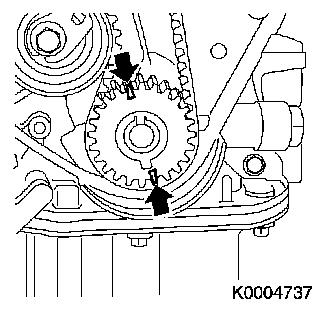
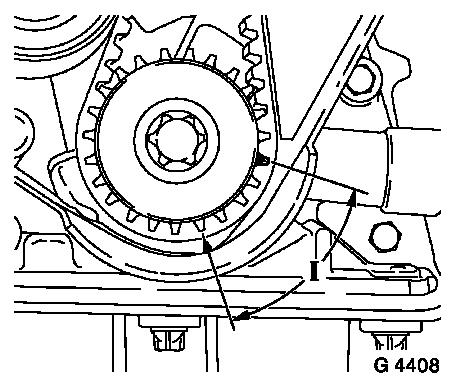
Apply aid marks.
| • |
On toothed belt drive belt.
Note: 180° offset
to the TDC cylinder 1 mark (arrow).
|
|
|
|
| 5. |
Turn crankshaft to ignition TDC marking, cylinder no. 1
|
| 8. |
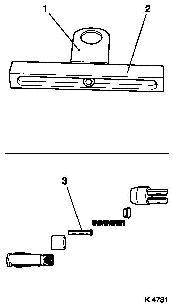
Complete valve spring lever automatic system.
| • |
Adjust supports.
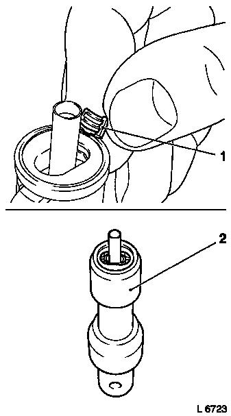
Note: Set support head
(1) centrally to the support feet (2) and tighten.
|
| • |
Complete lever arm.
| – |
With joint, removal head
|
|
| • |
Complete assembly head
| – |
For X 14 XE, Z 14 XE, X 16 XEL, Z 16 XE and Z 16 YNG use MKM-6086-100-1 and MKM-6086-100-10
|
| – |
For X 18 XE, Z 18 XE and Z 18 XEL use MKM-6086-200-1 and MKM-6086-200-10
|
| – |
Insert thrust piece (3)
|
|
|
|
|
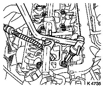
| 9. |
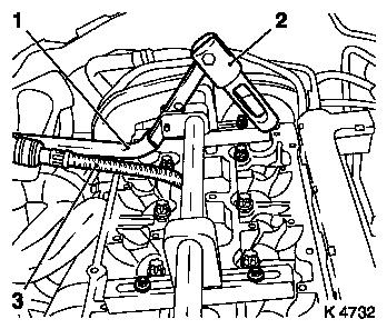
Attact valve spring lever automatic system
| • |
Attach supports
| – |
At camshaft bearing cover positions 1 and 4
|
| – |
Insert assembly shaft in supports
Note: Align assembly
shaft centrally via the spark plug bore
|
|
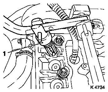
| • |
Attach lever arm (1)
Note: Removal head (2)
must point towards intake side
|
| • |
Secure installation shaft
|
|
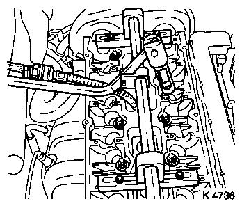
| 10. |
Fit compressed air adapter (3)
| • |
Screw into spark plug thread cylinder 1
|
| • |
Apply compressed air to cylinder 1
|
|
|
|
| 11. |
Remove intake valve springs on cylinder no. 1
| • |
Carefully push valve springs downwards
| – |
With lever arm
Note: Removal head must
stand vertically above valve stem
|
|
Important: Observe correct
assignment
|
| • |
Remove valve cotters, plates and springs
Note: Do not use
magnetic tools
|
|
| 12. |
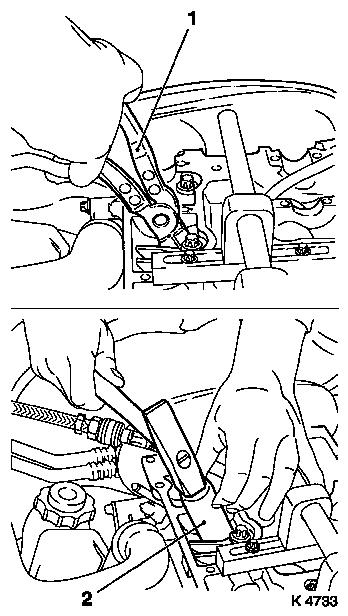
Replace valve stem seals
| • |
Place new valve shaft seal onto valve shaft
|
| • |
Drive to stop using KM-835-A (2)
|
|
|
|
| 13. |
Install intake valve springs, cylinder no. 1
| • |
Insert valve springs, plates
|
| • |
Insert valve cotters (1) in assembly head
| – |
Push clamping sleeve (2) towards the lever arm holder
|
Important: Insert valve cotters
with tapered end towards valve
|
| – |
Push clamping sleeve towards the valve
|
|
| • |
Attach assembly head to lever arm
|
| • |
Carefully push valve springs downwards
Important: Assembly head must
stand vertically above valve stem
|
| – |
With lever arm
Note: Valve cotters
must engage audibly
|
|
|
|
|
Important: Do not make a 2nd
attempt without checking that both valve cotters are in the
assembly head. Check valve cotter seat. Ensure application of
compressed air.
|
| 14. |
Check installation position
|
| 15. |
Convert lever arm
| • |
Install lever arm
Note: Removal head must
point towards exhaust side
|
|
| 16. |
Remove exhaust valve springs from cylinder no. 1
| • |
Carefully push valve springs downwards
| – |
With lever arm
Note: Dismantling head
(1) must be vertical position above valve stem
|
|
Important: Observe correct
assignment
|
| • |
Remove valve cotters, plates and springs
Note: Do not use
magnetic tools
|
|
|
|
| 17. |
Replace valve stem seals
| • |
Place new valve shaft seal onto valve shaft
|
| • |
Drive to stop using KM-835-A
|
|
| 18. |
Install exhaust valve springs on cylinder no. 1
| • |
Insert valve springs, plates
|
| • |
Insert valve cotters in assembly head
| – |
Push clamping sleeve towards the lever arm holder
|
Important: Insert valve cotters
with tapered end towards valve
|
| – |
Push clamping sleeve towards the valve
|
|
| • |
Attach assembly head to lever arm
|
| • |
Carefully push valve springs downwards
Important: Assembly head must
stand vertically above valve stem
|
| – |
With lever arm
Note: Valve cotters
must engage audibly
|
|
|
Important: Do not make a 2nd
attempt without checking that both valve cotters are in the
assembly head. Check valve cotter seat. Ensure application of
compressed air.
|
| 19. |
Check installation position
|
| 20. |
Convert compressed air adapter
| • |
Interrupt compressed air feed
|
| • |
Unscrew from spark plug thread cylinder 1
|
| • |
Screw into spark plug thread cylinder 4
|
| • |
Apply compressed air to cylinder 4
|
|
| 21. |
Convert lever arm
| • |
Secure installation shaft
|
|
|
|
| 22. |
Replace valve stem seals, cylinder no. 4
|
| 23. |
Interrupt compressed air feed
|
| 26. |
Set cylinder 3 to TDC of combustion stroke
| • |
Turn crankshaft evenly (180°)
Note: Alignment marking
of toothed belt drive wheel must align with marking at the rear of
the toothed belt cover
|
|
| 29. |
Transfer valve spring lever automatic system
| • |
Transfer supports
| – |
At camshaft bearing cover positions 1 and 5
|
| – |
Insert assembly shaft in supports
Note: Align assembly
shaft centrally via the spark plug bore
|
|
| • |
Install lever arm
Note: Removal head must
point towards intake side
|
| • |
Secure installation shaft
|
|
| 30. |
Transfer compressed air adapter
| • |
From spark plug thread cylinder 4
|
| • |
Screw into spark plug thread cylinder no. 2
|
| • |
Apply compressed air to cylinder 2
|
|
|
|
| 31. |
Replace valve stem seals, cylinder no. 2
|
| 32. |
Convert compressed air adapter
| • |
Interrupt compressed air feed
|
| • |
Unscrew from spark plug thread cylinder 2
|
| • |
Screw into spark plug thread cylinder 3
|
| • |
Apply compressed air to cylinder 3
|
|
| 33. |
Replace valve stem seals, cylinder no. 3
|
| 34. |
Interrupt compressed air feed
|
| 35. |
Detach valve spring lever automatic system
|
| 36. |
Remove compressed air adapter
|
| 37. |
Visually check components
| • |
Camshafts, camshaft bearing cover, hydraulic tappets, cylinder
head, ribbed V-belt, ribbed V-belt tensioner, ribbed V-belt pulley,
toothed belt drive, spark plugs
|
|
 Install
| 38. |
Install spark plugs
| • |
Tighten with KM-194-E
| – |
Tightening torque 25 Nm
|
|
|
| 41. |
Position crankshaft
Note: Set crankshaft to
60° before TDC combustion stroke on cylinder 1 (I)
|
|
|
| 43. |
Install all the hydraulic valve lifters
| • |
See operation "Hydraulic Valve Lifter, Remove and Install"
|
|
|
