|
Injection Nozzles, Remove and Install
Important: Lay
aside injector nozzle traverse and injector nozzle according to
sequence during removal to ensure their correct allocation during
reinstallation. In general, all injector nozzles are to be removed
and all seal rings replaced
 Remove Remove
| 1. |
Lock engine on no. 1 cylinder "Ignition TDC" 
|
| 3. |
Remove injection lines
| • |
For X 20 DTL, Y 20 DTL, Y 20 DTH up to MY 2003
|
| • |
For Y 20 DTH as of MY 2003, Y 22 DTR
|
|
| 4. |
Remove inlet manifold upper section
| • |
For X 20 DTL, Y 20 DTL, Y 20 DTH up to MY 2003
|
| • |
For Y 20 DTH as of MY 2003, Y 22 DTR
|
|
| 5. |
Detach oil leak line from injection nozzle traverse
|
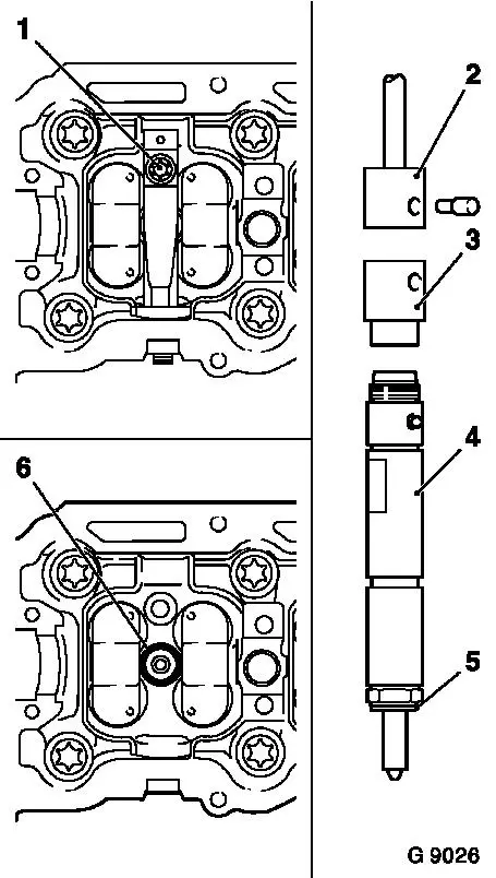
| 6. |
Remove fastening bolt (1)
| • |
Raise injector nozzle traverse slightly and press out of
cylinder head
|
|
| 7. |
Remove seal ring (6) from injection nozzle
|
| 8. |
Screw adapter KM-931 (3) onto
injection nozzle
|
| 9. |
Attach extraction tool KM-328-B (2)
to adapter and pull injection nozzle (4) out of cylinder head
|
| 10. |
Remove seal ring (5) from injector nozzle
|
|
|
 Install
| 11. |
Clean all removed parts and check for wear
|
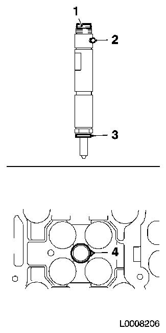
| 12. |
Install new rubber seal (1) and new copper seal ring (3) on
injection nozzle
|
| 13. |
Insert injection nozzles in cylinder head
| • |
Ball (2) must sit in the recess (4) in the cylinder head
|
|
|
|
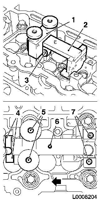
Important: The use of KM-6318 is mandatory in order to prevent damage
to the gaskets
|
| 14. |
Place KM-6318-2 (2) over camshaft
bearing 2 (3)
| • |
Ensure that the sliding surfaces (4) point to the control
side
|
|
| 15. |
Fit KM-6318-1 (1) on camshaft bearing
2
| • |
Note the displacement of the holes (7) of the camshaft bearing
and screws (5) from KM-6318-1
|
| • |
Stop (6) must be located on the transmission side of KM-6318-1
|
|
| 16. |
Slide KM-6318-2 in direction of arrow
until stop lies against KM-6318-1
|
|
|
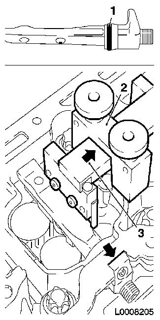
| 17. |
Shove new seal ring (1) on injector nozzle traverse
|
| 18. |
Carefully insert the injector nozzle traverse of cylinder 1 and
2 until it lies flush (arrow) in the cylinder head
| • |
If necessary, assist with light taps using plastic mallet
|
| • |
Ensure that no dirt enters the injector nozzle traverse as this
can cause malfunctions
|
|
| 19. |
Slide KM-6318-2 (3) in direction of
arrow, detach KM-6318-1 (2) from camshaft
bearing 2 and remove KM-6318-2
|
| 20. |
Repeat installation of injection nozzle traverse using KM-6318 for cylinders 3 and 4
|
|
|
Important: The tightening
procedure described in the following is the only way to guarantee
that the injection nozzle traverse is correctly tensioned on the
injection nozzle
|
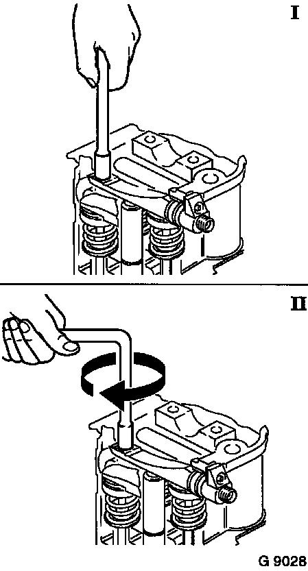
| 21. |
Insert traverse injection nozzle with new fastening bolt
| • |
I: Hand-tighten fastening bolt using torx nut and extension
(without toggle or ratchet)
|
| • |
II: Then turn another 360°
|
|
|
|
| 22. |
Attach new oil leak lines to injection nozzle traverse
|
| 24. |
Attach cylinder head cover
|
| 25. |
Install inlet manifold upper section
| • |
For X 20 DTL, Y 20 DTL, Y 20 DTH up to MY 2003
|
| • |
For Y 20 DTH as of MY 2003, Y 22 DTR
|
|
| 26. |
Install injection lines
| • |
For X 20 DTL, Y 20 DTL, Y 20 DTH up to MY 2003
|
| • |
For Y 20 DTH as of MY 2003, Y 22 DTR
|
|
|
