|
Fuel Injection Pump, Remove and Install
Important: For Y
20 DTH as of MY 2003, Y 22 DTR: Security code must be reset using
TECH2 before removal when replacing or swapping injection pump -
see relevant test instruction
 Remove Remove
| 1. |
Remove inlet manifold upper section
| • |
For X 20 DTL, Y 20 DTL, Y 20 DTH up to MY 2003 
|
| • |
For Y 20 DTH as of MY 2003, Y 22 DTR
|
|
| 2. |
Remove intake manifold lower part
|
| 3. |
Remove air cleaner housing with hot film mass air flow meter
and air intake hose
| • |
Y 20 DTH as of MY 2003 and Y 22 DTR
|
|
| 4. |
Lock engine on no. 1 cylinder "Ignition TDC"
|
| 5. |
Detach fuel lines from fuel injection pump
|
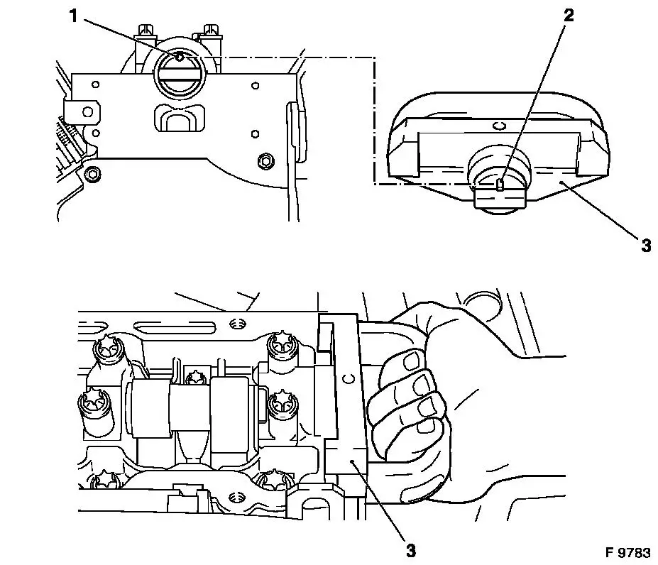
Important: To avoid bending the
pins and thus replacing the injection pump, protective caps KM-6154 must be fitted on the injection pump
immediately after removing the wiring harness plug and removed
again just before attaching the wiring harness plugs
|
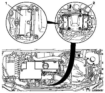
| 6. |
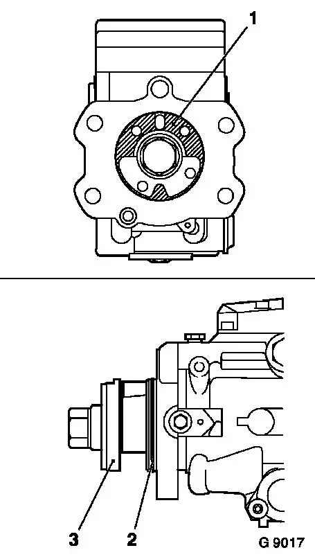
For Y 20 DTH from MY 2003, Y 22 DTR engine: Detach wiring
harness plugs (2) and attach KM-6154 (1)
to injection pump
|
|
|
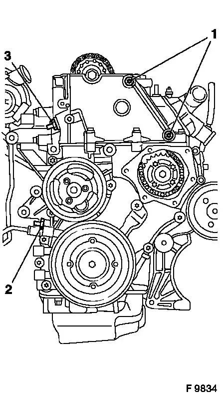
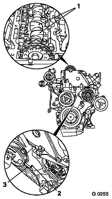
| 7. |
Remove Simplex chain tensioner (3)
| • |
Note installation position.
|
|
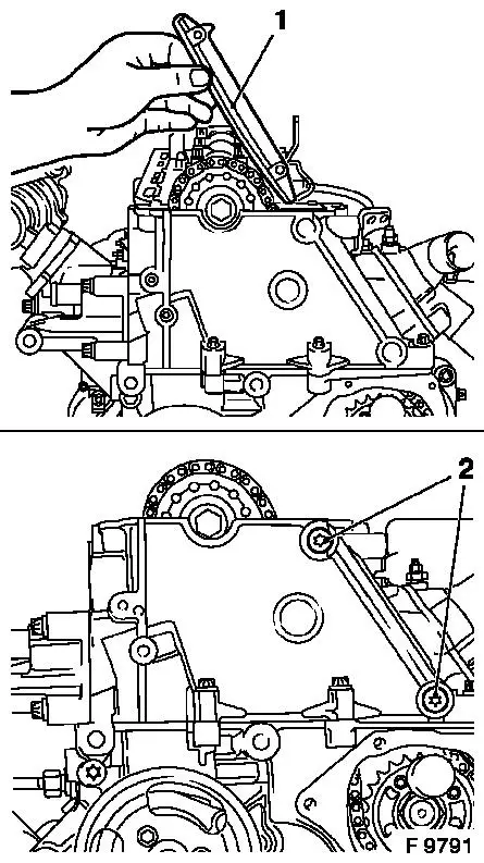
Important: Use sheet metal plate
or suitable heat shielding to avoid damaging the guide rails
|
| 8. |
Heat fastening bolts (1) intensively with hot air blower and
remove
|
| 9. |
Remove guide rail for simplex timing chain upwards
| • |
Note installation position.
|
|
| 10. |
Clean thread for the fastening bolts (1) in cylinder head
|
| 11. |
Remove duplex chain tensioner (2)
| • |
Note installation position.
|
|
|
|
| 12. |
Remove test gauge KM-932 from
cylinder head and injection pump locking pin KM-927 from retaining bore
|
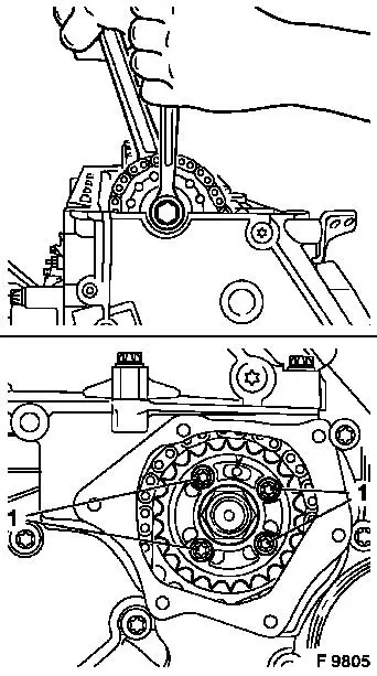
| 13. |
Remove camshaft sprocket from camshaft
Note: To simplify
installation, suspend simplex timing chain at suitable point
| • |
Counterhold with open-ended wrench on the hex nut of the
camshaft
|
|
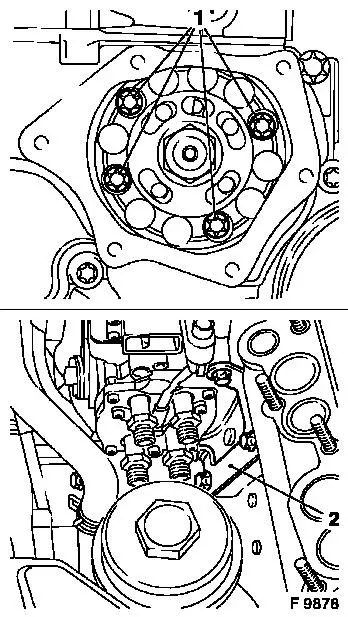
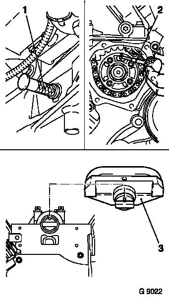
| 14. |
Remove fastening bolts (1) and simplex injection pump gear
Note: For Y 20 DTH from
MY 2003 and Y 22 DTR: 5 fastening bolts
|
| 15. |
Remove simplex timing chain upwards from cylinder head
|
|
|
| 16. |
Remove fastening bolts (1) from injection pump with MKM-604-D
|
| 17. |
Detach fuel injection pump bracket (2) from cylinder block and
fuel injection pump. Remove fuel injection pump towards rear out of
cylinder block and remove upwards out of engine compartment
|
|
|
 Install
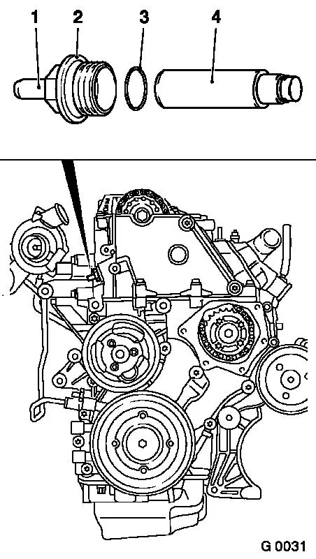
Important: The spacer disc (1) on
the fuel injection pump flange (3) must not be removed, as this
disc compensates for manufacturing tolerances and therefore
corresponds to a precisely defined axial dimension
|
| 18. |
Replace gasket (2)
|
| 19. |
Insert injection pump in cylinder block
| • |
Ensure that the duplex sprocket sits straight on the injection
pump flange without tilting
|
|
|
|
| 20. |
Injection pump to cylinder block
| • |
Tightening torque 25 Nm / 18.5 lbf.
ft.
|
|
| 21. |
Injection pump bracket to injection pump
| • |
Tightening torque 20 Nm / 15 lbf.
ft.
|
|
| 22. |
Fuel injection pump bracket to cylinder block
| • |
Tightening torque 20 Nm / 15 lbf.
ft.
|
|
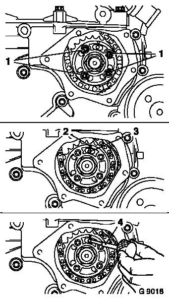
| 23. |
Guide simplex timing chain through timing case, and insert
simplex injection pump gear in simplex timing chain
| • |
Arrow (2) must align with recess in injection pump flange and
retaining bore (3) in injection pump
|
|
| 24. |
Loosely hand-tighten new fastening bolts (1) with bolt strength
10.9 of the simplex injection pump gear
Note: For Y 20 DTH from
MY 2003 and Y 22 DTR: 5 fastening bolts
|
| 25. |
Insert injection pump locking pin KM-927 (4) in retaining bore of fuel injection
pump
|
| 26. |
Insert camshaft sprocket in simplex timing chain and fasten
hand-tightened to camshaft with new fastening bolt
| • |
Ensure that the camshaft sprocket is not askew on the
camshaft
|
| • |
Camshaft sprocket must lie flat on the camshaft
|
|
|
|
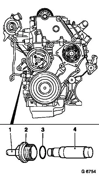
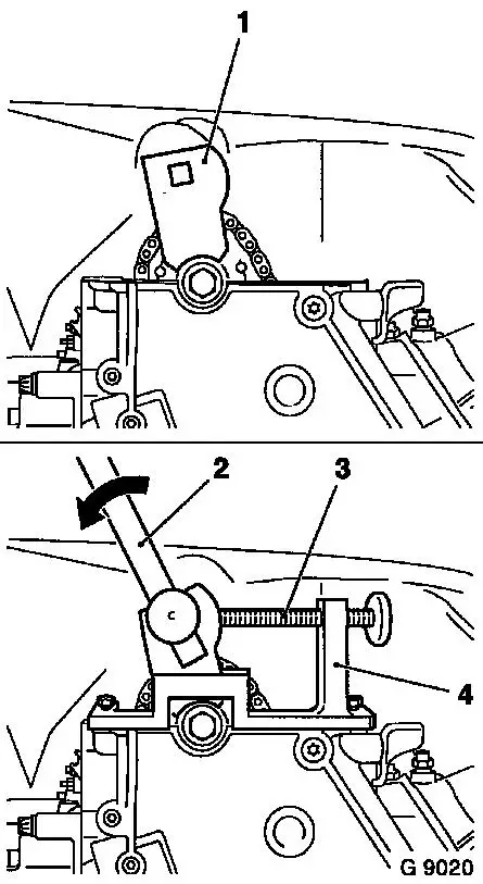
Important: A distinction must be
made between versions with and without release bolts (1). In
versions with release bolts, the chain tensioner must be
untightened using the release bolt after installation
|
| 27. |
Insert duplex chain tensioner (4) in timing case
| • |
The closed side of chain tensioner must point to tension rail.
Install duplex chain tensioner closure bolt (2) with new seal ring
(3)
|
| • |
Tightening torque 60 Nm / 44 lbf.
ft.
|
|
| 28. |
Press in the release pin with a hammer shaft until a click is
heard
|
| 29. |
It must be possible to push in release bolt up to stop with
thumb and for it to slide back to its original position
automatically
| • |
The release bolt can no longer be pushed in once the oil
pressure has built up
|
|
|
|
| 30. |
Remove injection pump locking pin KM-927
|
| 31. |
Tighten fastening bolts (1) for simplex injection pump gear
Note: For Y 20 DTH from
MY 2003 and Y 22 DTR: 5 fastening bolts
| • |
Tightening torque 28 Nm / 20.6 lbf.
ft.
|
|
| 32. |
Re-insert injection pump locking pin KM-927 into injection pump retaining bore
|
|
|
| 33. |
Position test gauge KM-932 (3) on
cylinder head
| • |
Pin (2) must engage in hole (1) of camshaft
|
|
|
|
| 34. |
Insert and install simplex timing chain guide rail (1)
Note: Check
installation position
| • |
Use new fastening bolts (2)
|
| • |
Tightening torque 8 Nm / 6 lbf.
ft.
|
|
|
|
| 35. |
Insert carrier (1) of adjuster KM-933
(4) vertically into camshaft sprocket. Mount adjuster KM-933 on cylinder head
|
| 36. |
Use toggle (2) to exert slight pressure on the carrier in the
direction of arrow (counter to direction of engine rotation) and
fix in place with locking bolt (3)
|
| 37. |
Injection pump locking pin KM-927
must be able to be installed and removed under suction. If this is
not possible, decrease the pressure on the carrier disc slightly
using the locking screw.
|
| 38. |
Fasten camshaft sprocket to camshaft
| • |
Tightening torque 90 Nm / 66 lbf. ft. +
60° + 30°
|
|
|
|
Important: A distinction must be
made between versions with and without release bolts (1). In
versions with release bolts, the chain tensioner must be
untightened using the release bolt after installation
|
| 39. |
Insert simplex chain tensioner (4) in cylinder head
| • |
The closed side of the chain tensioner must point to tension
rail. Install simplex chain tensioner closure bolt (2) with new
seal ring (3)
|
| • |
Tightening torque 60 Nm / 44 lbf.
ft.
|
|
| 40. |
Press in the release pin with a hammer shaft until a click is
heard
|
| 41. |
It must be possible to push in release bolt up to stop with
thumb and for it to slide back to its original position
automatically
| • |
The release bolt can no longer be pushed in once the oil
pressure has built up
|
|
|
|
| 42. |
Remove all locking and adjusting tools
|
| 43. |
At fastening bolt of torsional vibration damper, turn
crankshaft two turns (approx. 720°) in direction of engine
rotation to just before "1st cylinder TDC"
| • |
The mark (3) on the torsional vibration damper is located just
before the lug (2) on the timing case
|
|
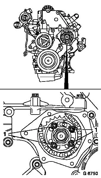
| 44. |
In this position, the cams (1) of the 1st cylinder are just
before TDC (both cams point upwards)
|
|
|
| 45. |
Insert crankshaft locking pin KM-929
(1) in aperture for crankshaft pulse pick-up, and simultaneously
slowly turn crankshaft further in engine rotational direction at
fastening bolt of torsional vibration damper until crankshaft lock
pin engages to stop in cylinder block or crank web
|
| 46. |
Insert fuel injection pump locking pin KM-927 (2) into injection pump retaining bore and
test gauge KM-932 (3) into cylinder
head
Note: If a tool cannot
be inserted, then the adjustment procedure must be completely
repeated
|
|
|
| 47. |
Remove all locking tools
|
| 48. |
Clean sealing surfaces on timing case cover and timing case
| • |
Cover aperture in timing case with lint-free cloth
|
|
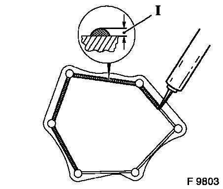
| 49. |
Apply an approx. 2 mm (Dimension I) thick bead of silicone
sealing compound to timing case cover.
Note: The silicone
sealing compound must be applied and the timing case must be
installed (including torque checking) within 10 minutes
|
|
|
| 50. |
Attach timing case cover to timing case with new fastening
bolts
| • |
Use 2 threaded pins (M6) to fasten
|
| • |
Tightening torque 6 Nm / 4.5 lbf.
ft.
|
|
| 51. |
Fit fuel lines on injection pump with new seal rings
| • |
Tightening torque 25 Nm / 18.5 lbf.
ft.
|
|
| 52. |
Attach crankshaft pulse pick-up to cylinder block with new
O-ring
| • |
Tightening torque 8 Nm / 6 lbf.
ft.
|
|
| 53. |
Install ribbed V-belt tensioner
|
| 55. |
Install cylinder head cover
|
| 56. |
Install air cleaner housing with hot film mass air flow meter
and air intake hose
| • |
Y 20 DTH as of MY 2003 and Y 22 DTR
|
|
| 57. |
For Y 20 DTH as of MY 2003, Y 22 DTR: Detach KM-6154 from injection pump and attach wiring harness
plug
|
| 58. |
Install intake manifold lower part
|
| 59. |
Install inlet manifold upper section
| • |
For X 20 DTL, Y 20 DTL, Y 20 DTH up to MY 2003
|
| • |
For Y 20 DTH as of MY 2003, Y 22 DTR
|
|
|
