|
Intake Manifold, Remove and Install (X 18 XE1)
 Remove Remove
|
Remove engine cover.
Remove air cleaner housing – see illustration "Air Ducts X
18 XE1, Z 18 XE, Z 18 XEL".
Remove ribbed V-belts – see operation "Ribbed V-belts,
Remove and Install".
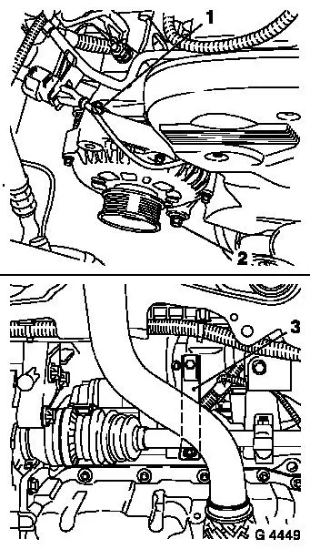
Release lower alternator fastening bolt (2).
Remove upper alternator fastening bolt (1) – twist
alternator rearwards.
Detach intake manifold support (3) from intake manifold and
release from cylinder block – swing support to one side.
|
|
|
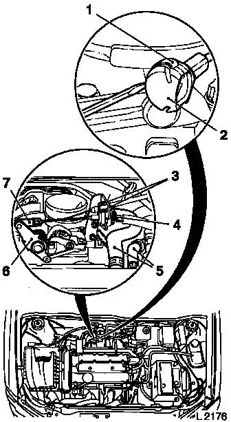
Press throttle valve lever (6) in direction of "full
acceleration" and hold in position.
Lift retainer (1) with screwdriver and remove ball socket (2)
from ball head.
If present: remove shackle for cruise control Bowden cable (7).
Compress guide for cruise control Bowden cable at the two pins (3)
and remove from bracket – lay cruise control Bowden cable
aside.
Disconnect retaining clamp (4) upwards and pull guide for
accelerator Bowden cable out of bracket and lay aside.
Remove engine vent hoses (5) from cylinder head cover.
|
|
|
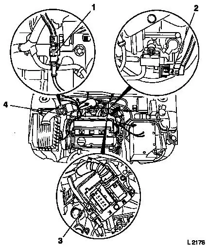
Detach or disconnect wiring harness plug for crankshaft pulse
pick-up (1) and wiring harness plug for switchover valve solenoid
valve (2) (accessible from underside of vehicle).
Detach or remove necessary cable connections which are connected
to the plug strip or cable bundle (4) and lay out of the way
– note cable routing. Disconnect plug strip with wiring
trough from injectors and lay aside.
Detach wiring harness (3) from engine control unit.
|
|
|
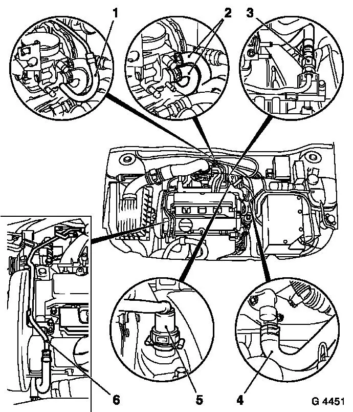
Remove hose for tank vent valve (1) from throttle body.
Detach coolant hoses (2) from throttle body – collect
escaping coolant.
Detach coolant line (6) from intake manifold and cylinder head
cover and place to one side.
Detach coolant hose (heater) (4) from intake manifold.
Reduce fuel pressure with Pressure Tester KM-J-34730-91 via
testing port – collect escaping fuel in suitable container
– observe safety regulations and national legislation.
Detach fuel feed line (3) from fuel distributor pipe.
Detach brake servo vacuum line (5) from intake manifold.
|
|
|
Detach rear engine transport shackle from cylinder head.
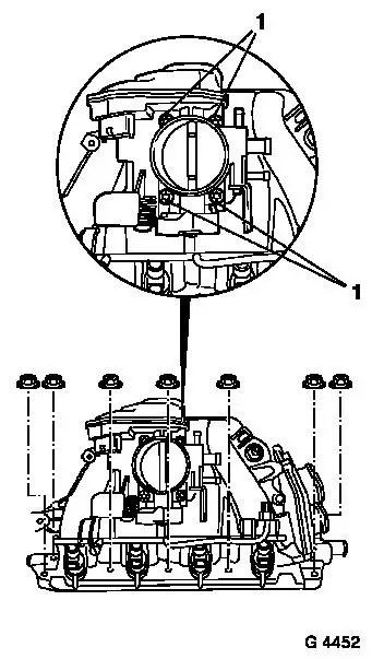
Remove fastening bolts (1) – remove throttle body from
intake manifold.
Detach intake manifold from cylinder head and remove.
 Clean Clean
Clean sealing surfaces and remove gasket residues.
|
|
 Install
Attach intake manifold to cylinder head with new gasket and new
fastening nuts – tightening torque 20 Nm / 15 lbf. ft.
Attach throttle body with new gasket to intake manifold –
tightening torque 8 Nm / 6 lbf. ft.
Attach engine transport shackle to cylinder head –
tightening torque 25 Nm / 18.5 lbf. ft.
Attach brake servo vacuum line to intake manifold.
Attach fuel line to fuel distributor pipe – tightening
torque 15 Nm / 11 lbf. ft.
Attach coolant line to intake manifold and cylinder head cover
– tightening torque 8 Nm / 6 lbf. ft.
Attach coolant hoses to throttle body and intake manifold.
Attach tank vent valve hose to throttle body.
Connect wiring harness plug to engine control unit and lock.
Connect plug strip to injectors – plug strip must audibly
engage.
Connect or attach all wiring connections connected to the
injectors plug strip.
Attach engine vent hoses to cylinder head cover.
If present: insert guide for cruise control Bowden cable into
bracket – ensure that both catches engage.
Install guide for accelerator Bowden cable in bracket and insert
retaining clamp behind intermediate washer.
Press throttle valve lever in direction of "full acceleration"
and hold in position.
Connect shackle for cruise control Bowden cable and ball socket
for accelerator Bowden cable to ball head – ensure that
retainer engages.
Attach alternator to shackle – tightening torque 20 Nm /
15 lbf. ft.
Attach or connect wiring harness plug for crankshaft pulse
pick-up and wiring harness plug for switchover valve solenoid valve
(accessible from underside of vehicle).
Attach intake manifold support to intake manifold –
tightening torque 20 Nm / 15 lbf. ft.
Fasten intake manifold support to cylinder block –
tightening torque 35 Nm / 26 lbf. ft.
Tighten lower alternator bolt – tightening torque 35 Nm /
25.8 lbf. ft.
Install ribbed V-belt – see operation "Ribbed V-belt,
Remove and Install".
Install air cleaner housing – see illustration "Air Ducts
X 18 XE1, Z 18 XE, Z 18 XEL".
Install engine cover.
 Inspect
Charge and bleed cooling system – see operation "Cooling
System, Charge and Bleed" and "Cooling System, Check for
Leaks".
|
