|
Oil Pump, Check
 Remove Remove
| 2. |
Clean sealing surfaces and remove gasket remnants.
|
| 3. |
Check oil pump housing cover, cylinder block and rotors for
damage
|
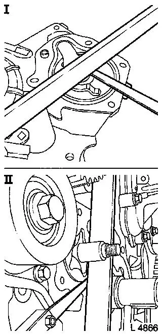
| 4. |
The bearing end play of the rotors in the oil pump housing is
measured with a straight edge and feeler gauge on the oil pump
housing cover (see figure I) and on the cylinder block (see fig.
II) and calculated mathematically.
|
Example:
|
|
I
|
|
2.120 mm
|
|
II
|
-
|
1.980 mm
|
| |
=
|
0.140 mm
|
|
Permissible bearing end play of the rotors in the oil pump
housing:
|
|
Play on installation
|
0.035 - 0.100 mm
|
|
Wear limit
|
0.150 mm
|
|
|
|
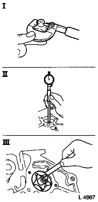
| 5. |
The radial bearing clearance of the pump shaft in the cylinder
block is measured with a micrometer (see figure I) and a precision
internal measuring device (see figure II) and calculated
mathematically
|
Example:
|
|
I
|
|
16.015 mm
|
|
II
|
-
|
15.900 mm
|
| |
=
|
0.115 mm
|
|
Permissible radial bearing clearance of the oil pump shaft in
the cylinder block:
|
|
Play on installation
|
0.040 - 0.125 mm
|
|
Wear limit
|
0.200 mm
|
|
| 6. |
Measure clearance between external rotor and cylinder block
with feeler gauge (see figure III)
|
Permissible clearance between external rotor and cylinder
block
|
|
Play on installation
|
0.240 - 0.360 mm
|
|
Wear limit
|
0.400 mm
|
|
|
|
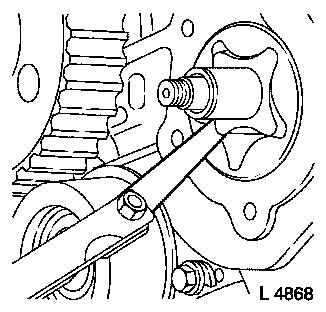
| 7. |
Check backlash of rotors with feeler gauge (see fig. I)
|
Permissible rotor backlash
|
|
Play on installation
|
0.130 - 0.150 mm
|
|
Wear limit
|
0.200 mm
|
Note: If the wear limit
of one or more components is reached, the oil pump is to be
replaced complete, consisting of the inner rotor, outer rotor and
oil pump housing cover.
|
|
|
 Install
|
