|
Adjust balancer shaft unit/crankshaft tooth
backlash
 Remove Remove
| 1. |
Remove lower engine splash guard
|
| 2. |
Disconnect catalytic converter control oxygen sensor wiring
harness plug
|
| 3. |
Remove front exhaust pipe
|
| 4. |
Remove oil drain bolt
Note: Collect engine
oil
|
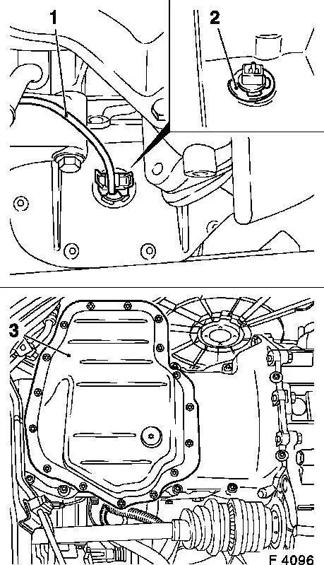
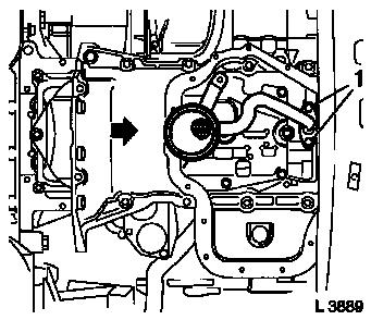
| 5. |
Disconnect wiring harness plug (1) for dynamic oil level
control and remove retaining ring (2)
|
| 6. |
Detach lower part of oil pan (3) from upper part of oil pan
|
|
|
| 7. |
Clean sealing surfaces and remove gasket remnants.
|
| 8. |
Remove oil filter from oil pump with KM-726-A
|
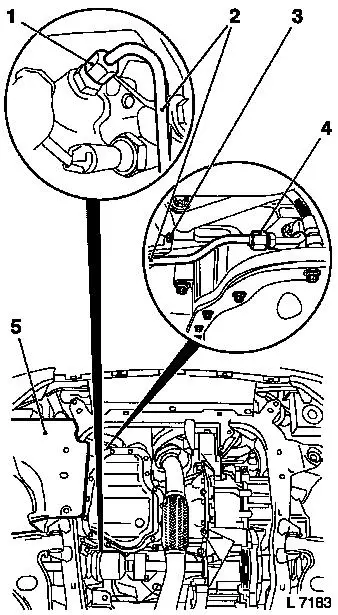
| 9. |
Detach union nut (4) from turbocharger oil feed line
(turbocharger)
Note: Place collecting
basin underneath.
|
| 10. |
Detach bracket (3) from cylinder block
|
| 11. |
Detach union nut (1) from cylinder block flange and remove
turbocharger oil feed line (cylinder block) (2)
|
|
|
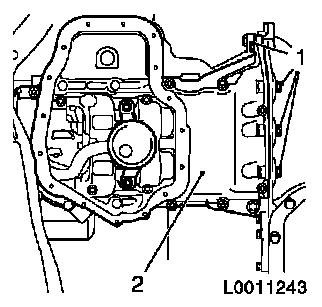
| 12. |
Detach oil pan top bolts (1) from transmission housing
|
| 13. |
Detach upper part of oil pan (2) from cylinder block and remove
oil pump
|
|
|
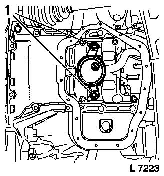
| 14. |
Detach 2x oil intake pipe bolts (1) from balancer shaft
unit
|
|
|
| 15. |
Move upper part of oil pan in direction of arrow and detach 2x
oil intake pipe bolts (1) from oil pump
|
| 16. |
Remove upper part of oil pan with oil intake pipe
|
|
|
| 17. |
Clean sealing surfaces and remove gasket remnants.
|
| 18. |
Detach oil baffle plate from balancer shaft unit.
|
Important: Only one balancer
piece may be installed
|
| 19. |
Detach balancer shaft unit from cylinder block and crankshaft
bearing cap and remove with balancer piece. For better allocation,
a number (identification) is located on the balancer piece. The
tooth backlash can also be adjusted using balancer pieces of
varying thickness.
|
Identification
|
Thickness of balancer piece in mm
|
|
55
|
0.535 to 0.565
|
|
58
|
0.565 to 0.595
|
|
61
|
0.595 to 0.625
|
|
64
|
0.625 to 0.655
|
|
67
|
0.655 to 0.685
|
|
70
|
0.685 to 0.715
|
|
73
|
0.715 to 0.745
|
|
76
|
0.745 to 0.775
|
|
79
|
0.775 to 0.805
|
|
82
|
0.805 to 0.835
|
|
85
|
0.835 to 0.865
|
Note: The next larger or
smaller balancer piece changes the tooth backlash by approx. 0.02
mm!
Example for selecting the balancer piece: with an installed
balancer piece with the mark "70" a tooth backlash of 0.08 mm was
determined. If a balancer piece with the mark "67" is then
installed, then this produces a tooth backlash of approx. 0.06
mm.
.
|
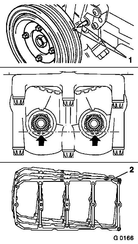
| 20. |
Turn the crankshaft in the direction of engine rotation to "1st
Cylinder TDC" (mark 1) using the fastening bolt for the toothed
belt drive gear.
|
| 21. |
Turn balancer shafts so that both flattened sides (arrows)
point downward and form a horizontal line.
|
| 22. |
Attach selected balancer piece (2) with balancer shaft unit to
cylinder block and crankshaft bearing cap
| • |
Tighten all bolts uniformly 20 Nm +
45°
|
|
|
|
| 23. |
Following installation of balancer shaft unit, tooth backlash
must be re-checked and, if necessary, adjusted.
Note: If the balancer
shaft unit needs to be replaced, use the thickest balancer piece
(identification "85") for the initial installation to ensure a
tooth backlash in any case.
|
 Install
| 24. |
Attach oil baffle plate to balancer shaft unit 8 Nm
|
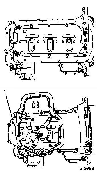
| 25. |
Apply a bead of adhesive sealing compound (black) to joints
(arrows) of oil pump and rear crankshaft bearing cap
|
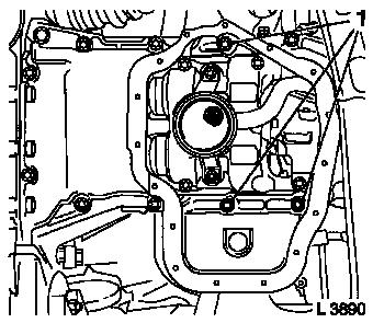
| 26. |
Insert upper part of oil pan (1) with new gasket and oil intake
pipe
|
| 27. |
Attach oil intake pipe to oil pump with new seal ring 8 Nm
1)
|
| 28. |
Attach oil intake pipe to balancer shaft unit 10 Nm
|
|
|
| 29. |
Attach upper part of oil pan to cylinder block, oil pump and
transmission housing with new gasket
|
| 30. |
Insert contact surfaces of bolts (1) coated with surface
sealant (green)
Installation sequence:
| 1. |
Tighten all bolts loosely. |
| 2. |
Tighten bolts at cylinder block and oil pump 20 Nm |
| 3. |
Tighten bolts at transmission housing 40 Nm . |
|
|
|
| 31. |
Insert turbocharger oil feed line (cylinder block) and attach
to cylinder block flange with union nut 20
Nm
|
| 32. |
Attach turbocharger oil feed line union nut (cylinder block) to
turbocharger oil feed line (turbocharger) 20 Nm
|
| 33. |
Attach turbocharger oil feed line bracket to cylinder block
35 Nm
|
| 34. |
Coat oil filter seal ring with a thin layer of engine oil and
attach to oil pump 15 Nm
|
| 35. |
Insert dynamic oil level control plug-in connection into upper
section of oil pan with new seal ring and fix in position with
retaining ring
|
| 36. |
Attach lower section of oil pan to upper section of oil pan
with new gasket and new bolts 8 Nm +
30°
|
| 37. |
Attach oil drain bolt to lower section of oil pan with new
gasket 10 Nm
|
| 38. |
Connect wiring harness plug for dynamic oil level control
|
| 39. |
Install front exhaust pipe with new gasket 35 Nm
|
| 40. |
Connect wiring harness plug for catalytic converter control
oxygen sensor
|
| 41. |
Route wiring harness
Note: Note routing of
wires
|
| 42. |
Install lower engine splash guard
|
| 43. |
Top up engine oil quantity to "MAX" mark on oil dipstick
|
1 ) Recut thread before use and insert bolts with
bolt locking compound (red). Installation time including torque
check should not exceed 10 minutes.
|
