|
Valve Lash - Petrol Engine, Check and Adjust
 Remove Remove
| 2. |
Disconnect battery
| • |
Detach earth connection from earth terminal
|
|
| 3. |
Remove air cleaner housing
- A 16 XER, Z 16 XER
- A 18 XER, Z 18 XER
|
| 4. |
Remove front toothed belt cover (top) 
|
| 5. |
Remove cylinder head cover
|
| 6. |
Raise vehicle by its full height
|
| 7. |
Remove ribbed V-belt tensioner
|
| 8. |
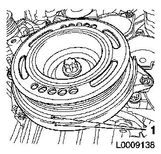
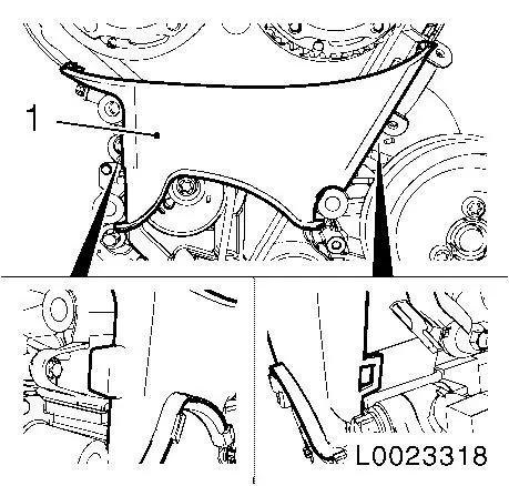
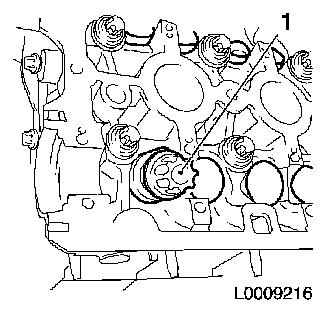
Set engine to TDC
| • |
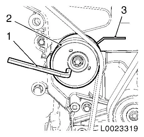
Turn crankshaft in the direction of engine rotation by the bolt
of the torsional vibration damper to cylinder 1 TDC of combustion
stroke
|
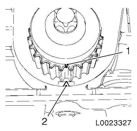
| • |
Marking on torsional vibration damper must align with the
marking on the lower part of the toothed belt cover (1)
|
|
|
|
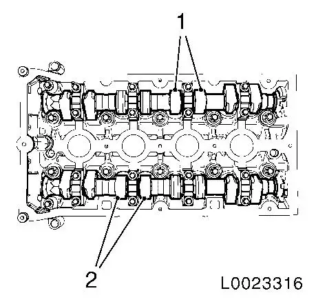
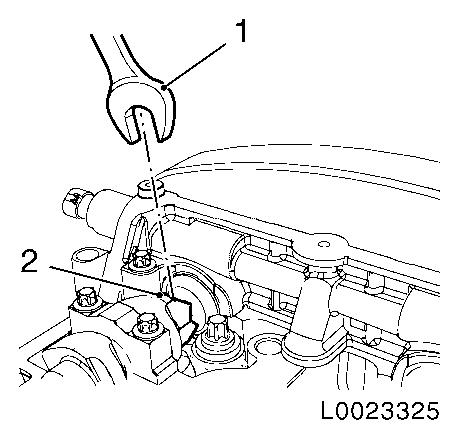
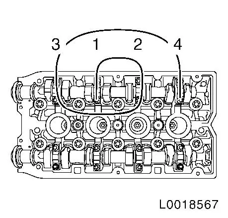
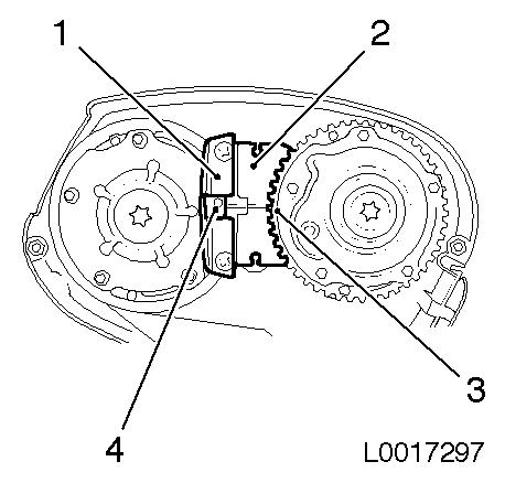
| 9. |
Cams at the intake side of cylinder no.2 (1) and the exhaust
side of cylinder no.3 (2) are on top and tilted slightly towards
the inside to the same extent
|
|
|
| 10. |
Check valve lash
| • |
Prescribed valve lash
| – |
Intake valves 0.21 - 0.29 mm
(nominal value 0.25 mm )
|
| – |
Exhaust valves 0.27 - 0.35 mm
(nominal value 0.30 mm )
|
|
|
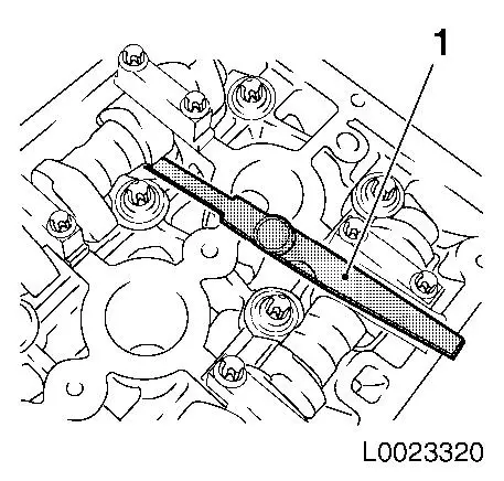
| 11. |
Check 4x valve clearance
| • |
Check valve lash with KM-6361 (1)
|
|
|
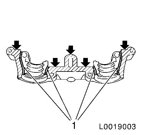
|
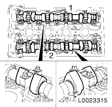
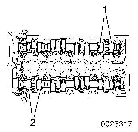
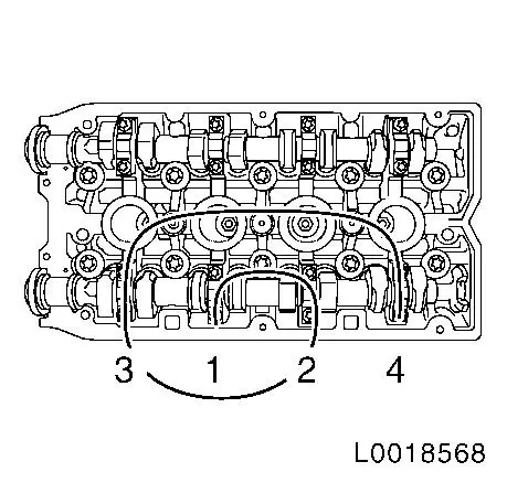
| 12. |
Rotate crankshaft on torsional vibration damper bolt by
180°
| • |
In direction of engine rotation.
| – |
Pairs of cams (1) and (2) point upwards at an angle
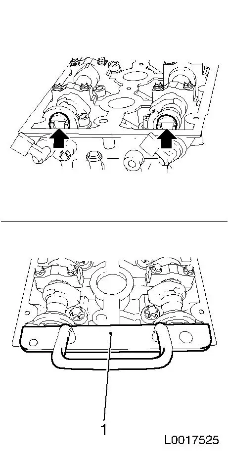
|
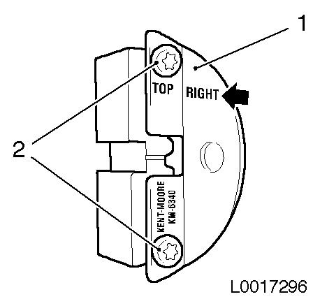
|
|
|
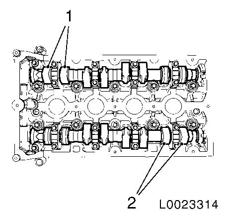
|
| 13. |
Check 4x valve clearance
| • |
Check valve lash with KM-6361
|
|
| 14. |
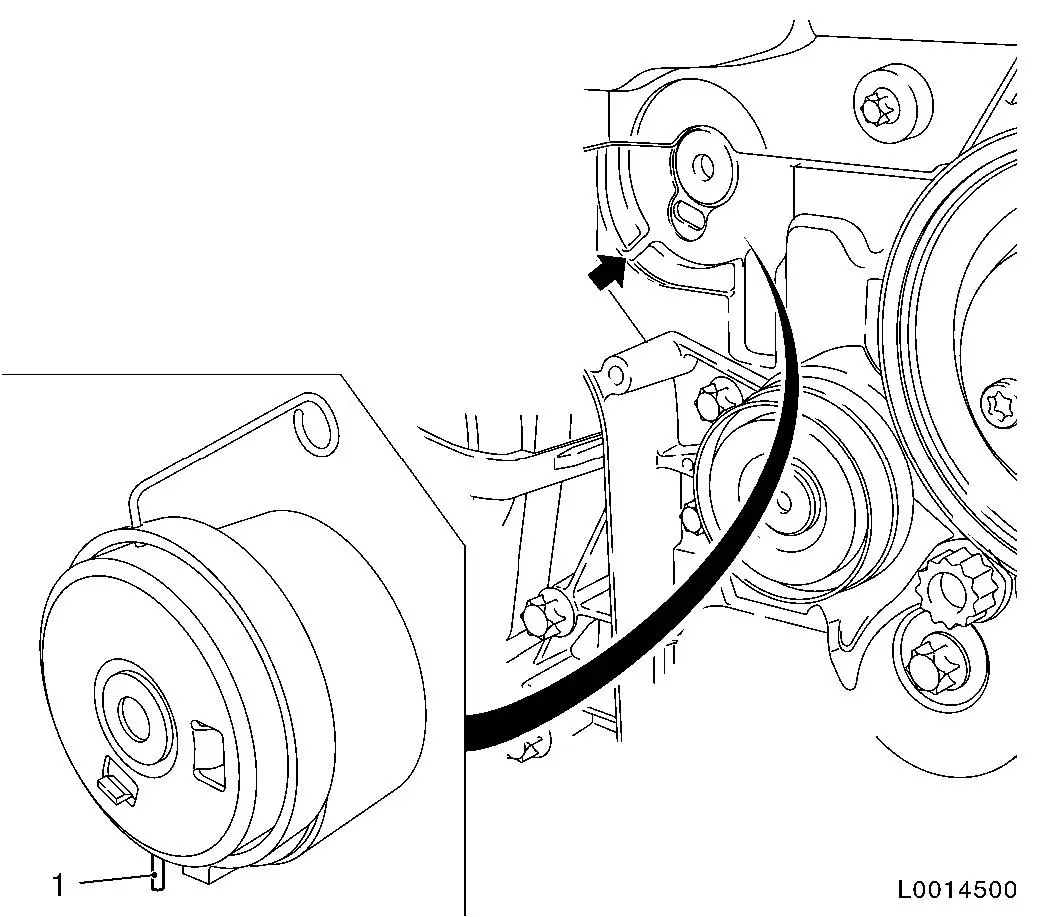
Rotate crankshaft on torsional vibration damper bolt by
180°
| • |
In direction of engine rotation.
| – |
Pairs of cams (1) and (2) point upwards at an angle
|
|
|
|
|
| 15. |
Check 4x valve clearance
| • |
Check valve lash with KM-6361
|
|
| 16. |
Rotate crankshaft on torsional vibration damper bolt by
180°
| • |
In direction of engine rotation.
| – |
Pairs of cams (1) and (2) point upwards at an angle
|
|
|
|
|
| 17. |
Check 4x valve clearance
| • |
Check valve lash with KM-6361
|
|
| 18. |
Rotate crankshaft on torsional vibration damper bolt by
180°, to TDC of combustion stroke of cylinder 1
|
| 19. |
Raise vehicle by its full height
|
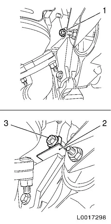
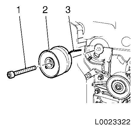
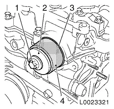
| 20. |
Immobilise crankshaft via starter ring
| • |
Attach KM-6625
| – |
Detach screwed connection (1)
|
| – |
Tighten screwed connection (3)
|
|
|
|
|
| 21. |
Remove torsional vibration damper
|
| 22. |
Remove front toothed belt cover (bottom)
|
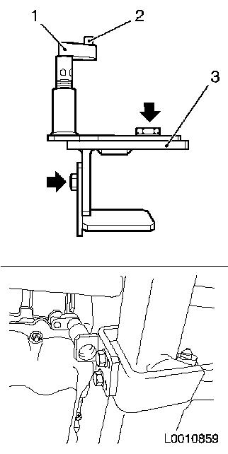
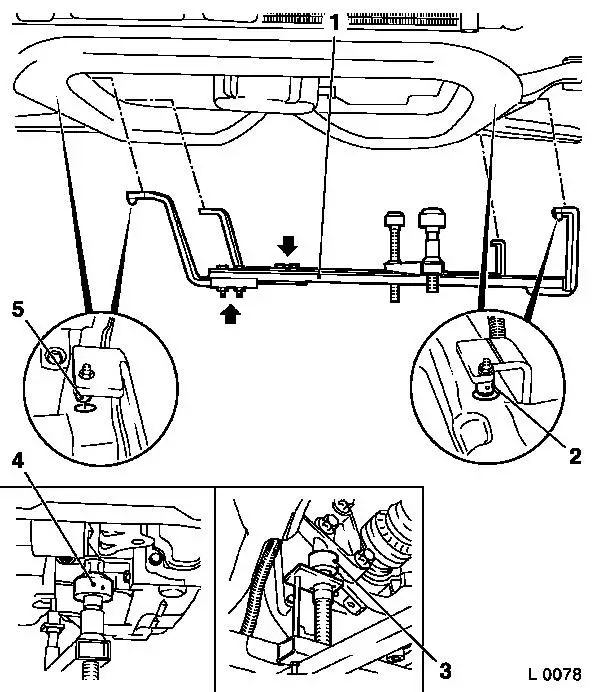
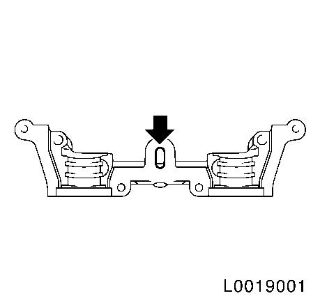
| 23. |
Insert KM-6173 (3)
| • |
Slacken 4x bolts (arrows) and hand-tighten
|
| • |
Align KM-6173 at front axle body
|
| • |
Wind up the support bearing (1)
| – |
Journal (2) must sit in mount at cylinder block
|
|
|
|
|
|
| 24. |
Attach KM-6001-A (1)
Note: Attaching KM-6001-A guarantees perfect alignment of the
drive unit with the front axle body.
| • |
Slacken 3x bolts (arrows) in adjusting rails
|
| • |
Insert KM-6001-A
| – |
The journals (2) and (5) must sit in the guide holes of the
front axle body
|
|
| • |
Tighten 3x bolts in adjusting rails
|
| • |
Adjust support bearings, front (4) and rear (3)
| – |
Raise support bearings up to the stop on the guide journals
Note: The guide
journals must be seated free from play in the support bearings.
|
|
|
|
| 25. |
Lower vehicle by its full height
|
| 26. |
Remove engine damping block, right hand side
|
|
|
| 27. |
Remove engine damping block support (1)
|
|
|
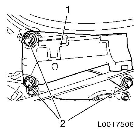
| 28. |
Remove front toothed belt cover (centre) (1)
| • |
Unclip 2x from rear of toothed belt cover
|
|
|
|
| 29. |
Stop toothed belt tensioner
| • |
Apply tension to toothed belt tension roller (2) clockwise
using an Allen key (1), and fix using KM-6333 (3)
|
|
|
|
| 31. |
Remove toothed belt tensioner (2)
Note: Do not remove
locking using KM-6333 (3).
|
|
|
| 32. |
Raise vehicle by its full height
|
| 33. |
Attach fastening bolt with washer to the torsional vibration
damper of the crankshaft. Tighten by hand.
|
| 34. |
Remove KM-6625
| • |
Detach screwed connection
|
|
| 35. |
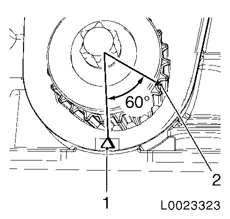
Turn the crankshaft 60° against the direction of engine
rotation to the fastening bolt of the torsional vibration
damper
Note: Check using the
TDC marks on the toothed belt drive gear (1) and oil pump housing
(2)
|
|
|
| 36. |
Lower vehicle by its full height
|
| 37. |
Place collecting basin underneath.
|
| 38. |
Unscrew closure bolt, exhaust camshaft adjuster
|
| 39. |
Unscrew intake camshaft closure bolt
|
| 40. |
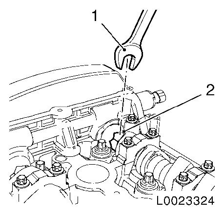
Slacken exhaust camshaft adjuster
Note: 2 mechanics
required
| • |
Counterhold against the camshaft hex (2) using an open-ended
spanner socket (1)
|
|
|
|
| 41. |
Detach exhaust camshaft adjuster
|
| 42. |
Slacken intake camshaft adjuster
Note: 2 mechanics
required
| • |
Counterhold against the camshaft hex (2) using an open-ended
spanner socket (1)
|
|
|
|
| 43. |
Detach intake camshaft adjuster
|
| 44. |
Remove rear toothed belt cover
| • |
Unclip wiring trough cover
|
|
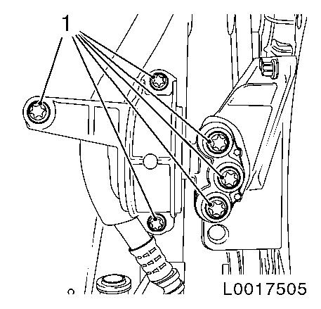
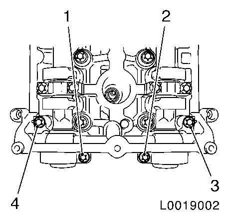
| 45. |
Remove camshaft bearing support
| • |
Unscrew 4x bolts
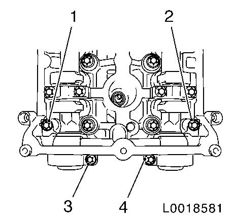
| – |
Note removal sequence 1 - 4
|
|
| • |
Release bearing support by striking it gently with a plastic
hammer
|
|
|
|
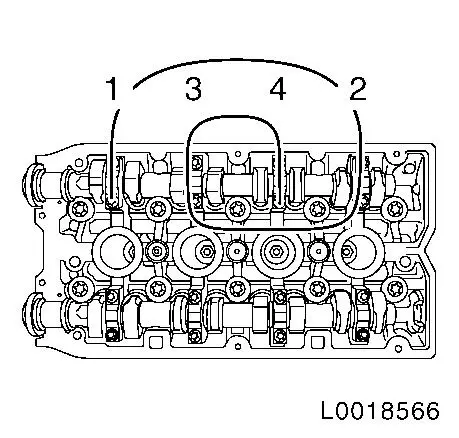
| 46. |
Remove intake camshaft
Note: Mark the camshaft
bearing caps before removing them.
| • |
Slacken camshaft bearing caps 1 - 4, working in spiral from
outside to inside in steps of 1/2 up to 1 turn
|
| • |
Remove the camshaft bearing cover from the cylinder head and
take out the camshaft
Note: Note marking on
the camshaft bearing cap with stamped numbers from 1 to 8 (there is
a dot at bottom left before each number to avoid mistakes).
|
|
|
|
|
| 47. |
Remove exhaust camshaft
Note: Mark the camshaft
bearing caps before removing them.
| • |
Slacken camshaft bearing caps 5 - 8, working in spiral from
outside to inside in steps of 1/2 up to 1 turn
|
| • |
Remove the camshaft bearing cover from the cylinder head and
take out the camshaft
Note: Note marking on
the camshaft bearing cap with stamped numbers from 1 to 8 (there is
a dot at bottom left before each number to avoid mistakes).
|
|
|
| 48. |
Remove cup tappet with KM-845 (1)
|
|
|
| 49. |
Determine cup tappet size
|
Example of determining the size of a cup tappet,
intake side:
|
|
Dimension of fitted cup tappet
|
|
3.20 mm
|
(Identification no. 20)
|
|
Valve clearance measurement between cams and cup tappets
|
+
|
0.35 mm
|
|
| |
=
|
3.55 mm
|
|
|
Required value, valve lash, intake side
|
-
|
0.25 mm
|
|
|
Nominal dimension of the new cup tappet
|
|
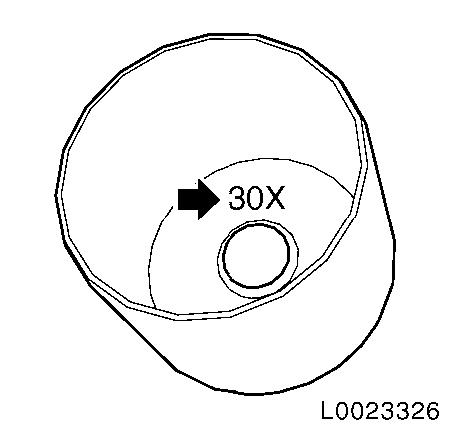
3.30 mm
|
(Identification number 30X)
|
Note: The identification
number (arrow) is on the inside of the cup tappet
| • |
Now use a cup tappet with this dimension or one that is nearest
to it
Currently available cup tappet sizes
|
|
|
|
 Install
| 50. |
Insert cup tappet with KM-845
| • |
Lightly coat sliding surfaces with oil
|
|
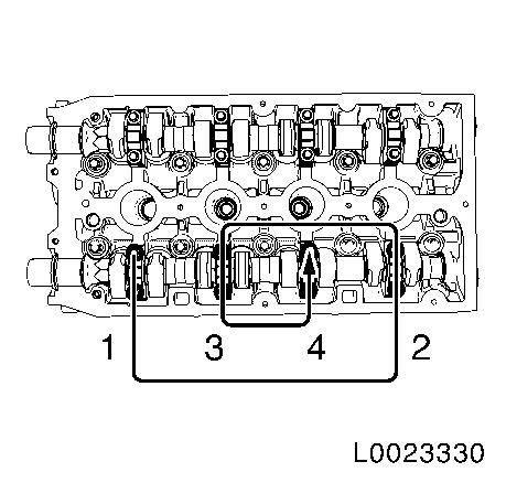
| 51. |
Install intake camshaft
| • |
Coat with MoS 2 lubricating paste
|
| • |
Insert camshaft
Note: Note the
identification marking on the camshaft bearing cover.
|
| • |
Install camshaft bearing cover
| – |
Tighten camshaft bearing caps 1 - 4 in a spiral from the inside
outward 8 Nm
Note: Note correct
tightening sequence 1 - 4.
|
|
|
|
|
| 52. |
Install exhaust camshaft
| • |
Coat with MoS 2 lubricating paste
|
| • |
Insert camshaft
Note: Note the
identification marking on the camshaft bearing cover.
|
| • |
Install camshaft bearing cover
| – |
Tighten camshaft bearing caps 1 - 8 in a spiral from the inside
outward 8 Nm
Note: Note correct
tightening sequence 1 - 4.
|
|
|
|
|
| 53. |
Clean sealing surfaces of 1st camshaft bearing support and the
cylinder head with a suitable tool, e.g. plastic wedge
| • |
Free oil duct (arrow) from any sealant residue
|
|
|
|
| 54. |
Place the camshaft bearing cap on the cylinder head without
sealant and hand-tighten the bolts (approx. 2 Nm )
Note: Note correct
tightening sequence 1 - 4.
|
|
|
| 55. |
Fit the camshaft adjuster for the intake camshaft to the intake
camshaft
|
| 56. |
Fit the camshaft adjuster for the exhaust camshaft to the
exhaust camshaft
|
Important: If the actual value
deviates from the required value, these values must be noted and
the adjustment procedure repeated
|
| 57. |
Check the valve clearance at both intake valves for cylinder
1
| • |
Turn the intake camshaft to the camshaft adjuster bolt in the
direction of engine rotation until the cams for cylinder 1 are
located in test position (1)
|
| • |
Insert feeler gauge EN-6361 and check
valve clearance
Note: Required value,
intake side valve clearance: 0.25 mm
|
|
|
|
| 58. |
Check the valve clearance at both intake valves for cylinder
3
| • |
Turn the intake camshaft to the camshaft adjuster bolt in the
direction of engine rotation until the cams for cylinder 3 are
located in test position
|
| • |
Insert feeler gauge EN-6361 and check
valve clearance
Note: Required value,
intake side valve clearance: 0.25 mm
.
|
|
| 59. |
Check the valve clearance at both intake valves for cylinder
4
| • |
Turn the intake camshaft to the camshaft adjuster bolt in the
direction of engine rotation until the cams for cylinder 4 are
located in test position
|
| • |
Insert feeler gauge EN-6361 and check
valve clearance
Note: Required value,
intake side valve clearance: 0.25 mm
.
|
|
| 60. |
Check the valve clearance at both intake valves for cylinder
2
| • |
Turn the intake camshaft to the camshaft adjuster bolt in the
direction of engine rotation until the cams for cylinder 2 are
located in test position
|
| • |
Insert feeler gauge EN-6361 and check
valve clearance
Note: Required value,
intake side valve clearance: 0.25 mm
.
|
|
Important: If the actual value
deviates from the required value, these values must be noted and
the adjustment procedure repeated
|
| 61. |
Check the valve clearance at both exhaust valves for cylinder
4
| • |
Turn the exhaust camshaft to the camshaft adjuster bolt in the
direction of engine rotation until the cams for cylinder 4 are
located in test position (1)
|
| • |
Insert feeler gauge EN-6361 and check
valve clearance
Note: Required value,
exhaust side valve clearance: 0.30
mm
|
|
|
|
| 62. |
Check the valve clearance at both exhaust valves for cylinder
2
| • |
Turn the exhaust camshaft to the camshaft adjuster bolt in the
direction of engine rotation until the cams for cylinder 2 are
located in test position
|
| • |
Insert feeler gauge EN-6361 and check
valve clearance
Note: Required value,
exhaust side valve clearance: 0.30
mm
|
|
| 63. |
Check the valve clearance at both exhaust valves for cylinder
1
| • |
Turn the exhaust camshaft to the camshaft adjuster bolt in the
direction of engine rotation until the cams for cylinder 1 are
located in test position
|
| • |
Insert feeler gauge EN-6361 and check
valve clearance
Note: Required value,
exhaust side valve clearance: 0.30
mm
|
|
| 64. |
Check the valve clearance at both exhaust valves for cylinder
3
| • |
Turn the exhaust camshaft to the camshaft adjuster bolt in the
direction of engine rotation until the cams for cylinder 3 are
located in test position
|
| • |
Insert feeler gauge EN-6361 and check
valve clearance
Note: Required value,
exhaust side valve clearance: 0.30
mm
|
|
| 65. |
Detach camshaft adjuster for intake camshaft
| • |
Counterhold against the intake camshaft hex
|
|
| 66. |
Detach camshaft adjuster for exhaust camshaft
| • |
Counterhold against the exhaust camshaft hex
|
|
| 67. |
Detach camshaft bearing support
|
Important: It is necessary to
ensure that no sealant is applied outside the designated sealing
surfaces.
|
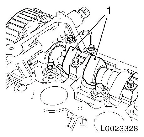
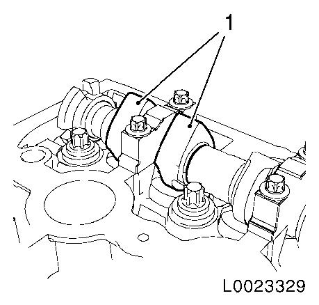
| 68. |
Apply surface sealant to sealing surfaces (arrows) of the
camshaft bearing support thinly and evenly
Note: The grooves (1)
adjacent to the sealing surfaces must remain free from sealant.
|
|
|
| 69. |
Place the camshaft bearing support on the cylinder head and
hand-tighten the bolts (approx. 2 Nm
)
Note: Note correct
tightening sequence 1 - 4.
|
|
|
| 70. |
Install 2x camshaft seal ring
| • |
Hoist the seal ring (3) using KM-422
(4) on the camshaft until this abuts against the cylinder head
| – |
To install, use camshaft sprocket bolt (1) in conjunction with
shims (2) with a total thickness of approx. 10 mm
|
|
|
|
|
| 71. |
Tighten the camshaft bearing support
Important: No sealant may reach
the camshafts.
|
| • |
Tighten 4x bolt 8 Nm
| – |
Note correct tightening sequence 1-4
|
|
|
|
|
| 72. |
Clean 4x thread, rear toothed belt cover
|
| 73. |
Install rear toothed belt cover
| • |
Tighten 4x new bolt 6 Nm
| – |
Coat 4x bolt with locking compound
|
|
| • |
Clip in wiring trough cover
|
|
| 74. |
Attach exhaust camshaft adjuster
| • |
Insert new sealing sleeve in adjuster
|
|
| 75. |
Attach intake camshaft adjuster
| • |
Insert new sealing sleeve in adjuster
|
|
| 76. |
Insert KM-6328-A (1) into
camshafts
Note: Align camshafts
horizontally by the hexagon until KM-6328-A (1) can be inserted in the grooves
(arrows)
|
|
|
| 77. |
Prepare KM-6340-Right for use on
engines A16XER, Z16XER, A18XER and Z18XER
| • |
Detach front panel (1) from KM-6340-Right
Unscrew 2x bolts (2)
|
|
|
|
| 78. |
Insert KM-6340 into camshaft
sprockets
Insert KM-6340-Left (1) and KM-6340-Right (2) in the camshaft adjuster as
shown
Note: The spot-type
marking (4) on the intake camshaft adjuster does not correspond to
the groove of KM-6340-Left during this
process but must be somewhat above as shown
The spot type marking (3) on the exhaust camshaft adjuster must
correspond to the groove on KM-6340-Right
|
|
|
| 79. |
Fasten exhaust camshaft adjuster
Note: 2 mechanics
required
| • |
Tighten bolt 65
Nm+125°+15°
|
| • |
Counterhold at camshaft hexagon
|
|
| 80. |
Fasten intake camshaft adjuster
Note: 2 mechanics
required.
| • |
Tighten bolt 65
Nm+125°+15°
|
| • |
Counterhold at camshaft hexagon
|
|
| 81. |
Tighten exhaust camshaft adjuster closure bolt 30 Nm
|
| 82. |
Tighten closure bolt, intake camshaft adjuster 30 Nm
|
| 84. |
Raise vehicle by its full height
|
| 85. |
Rotate the crankshaft about 60° in the direction of engine
rotation against the torsional vibration damper bolt
| • |
Marking, toothed belt drive gear (1) and oil pump housing (2)
must align
|
|
|
|
| 86. |
Block crankshaft.
| • |
Insert KM-6625
| – |
Install bolted connection
|
|
|
| 87. |
Lower vehicle by its full height
|
| 88. |
Clean thread, toothed belt tensioner
|
|
| 89. |
Intake toothed belt tensioner
| • |
Insert toothed belt tension roller
| – |
Free leg of spring (1) of the toothed belt tension roller must
engage in the cut-out (arrow) of the pump module
|
|
| • |
Tighten bolt 20 Nm + 120° +
15°
|
|
|
| 90. |
Remove fastening bolt with washer from the torsional vibration
damper of the crankshaft
|
Important: Use assembly tool.
|
| 91. |
Insert toothed belt
|
| 92. |
Release tension on toothed belt tensioner
| • |
Apply preliminary tension clockwise to toothed belt tension
roller
|
|
| 93. |
Raise vehicle by its full height
|
| 94. |
Install front toothed belt cover (lower)
|
| 95. |
Install torsional vibration damper
Important: Use new bolt.
|
| • |
Tighten bolt 95 Nm + 45° +
15°
|
|
| 96. |
Remove KM-6625
| • |
Detach screwed connection
|
| • |
Tighten screwed joint 40 Nm
|
|
| 97. |
Lower vehicle by its full height
|
| 99. |
Check position of camshaft sprockets
| • |
Turn crankshaft 720° in the direction of engine rotation by
the bolt on the torsional vibration damper
Note: Note marking,
camshaft sprockets.
|
| • |
Insert KM-6340 into camshaft
sprockets
|
|
| 100. |
Check camshaft positions
Insert KM-6628-A into camshafts
Note: If KM-6628-A cannot be inserted in the camshafts, the
timings must be set
|
| 101. |
Raise vehicle by its full height
|
| 102. |
Check crankshaft position
| • |
Marking on torsional vibration damper must align with the
marking (1) on the lower part of the toothed belt cover
|
|
|
|
| 103. |
Lower vehicle by its full height
|
| 104. |
Insert front toothed belt cover (centre)
| • |
Clip 2x onto the rear toothed belt cover
|
|
| 105. |
Install support for engine damping block
|
| 106. |
Install engine damping block
| • |
Fasten engine bracket adapter
|
| • |
Fasten engine damping block
|
|
| 107. |
Raise vehicle by its full height
|
| 108. |
Remove KM-6001-A
| • |
Slacken 3x screwed connections
|
|
| 110. |
Clean thread of bolt, ribbed V-belt tensioner
|
| 111. |
Install ribbed V-belt tensioner
|
| 112. |
Lower vehicle by its full height
|
| 114. |
Install cylinder head cover
|
| 116. |
Install front toothed belt cover (top)
|
| 117. |
Install air cleaner housing
- A 16 XER, Z 16 XER
- A 18 XER, Z 18 XER
|
| 118. |
Connect battery
| • |
Attach ground connection to ground terminal
|
|
| 119. |
Program volatile memories
|
|
