|
Check and adjust valve play
 Remove Remove
| 3. |
| 1. |
Remove air cleaner housing - Z16XEP  |
| 2. |
Remove air cleaner housing - Z16XE1 |
|
| 4. |
Remove DIS-ignition module
| • |
Remove cover of DIS-ignition module in the direction of the
arrow
Note: Note arrow on
cover
|
| • |
Remove from spark plugs using KM-6009
(1)
|
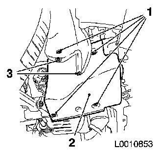
|
|
|
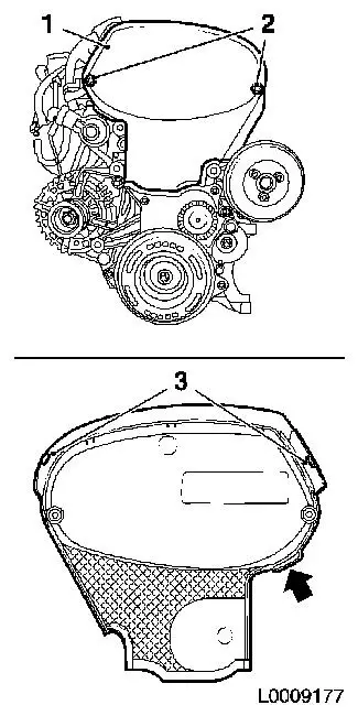
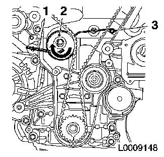
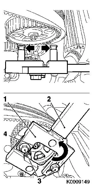
| 5. |
Detach front toothed belt cover (top) (1)
| • |
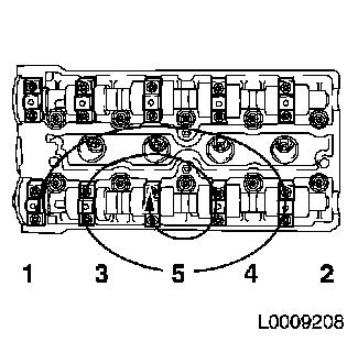
Release upper catch (3)
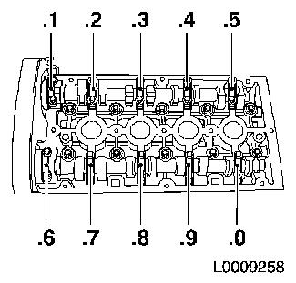
|
| • |
Pull front toothed belt cover (top) upwards by cast projection
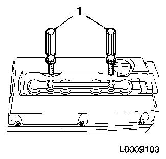
(arrow), applying slight tension
|
|
|
|
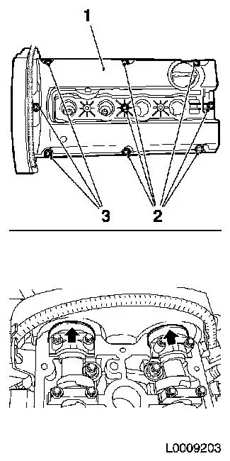
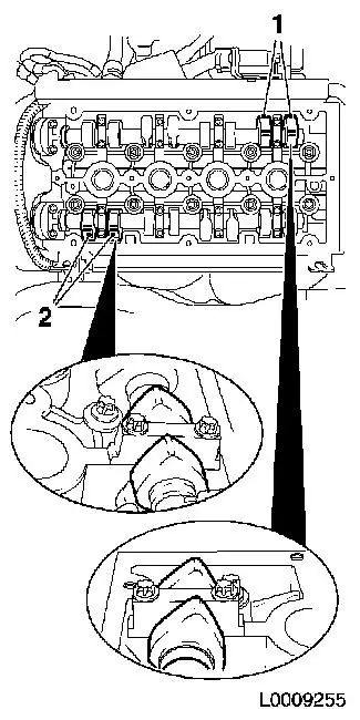
| 6. |
Detach cylinder head cover (1)
| • |
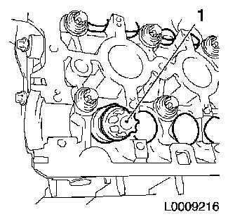
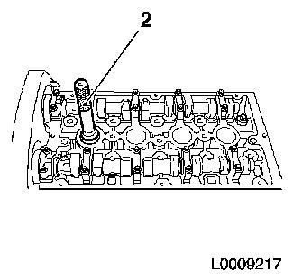
Unlatch and remove engine vent pipe
|
| • |
Slacken 3x bolt (3) pull upwards and fix in this position with
adhesive tape
|
| • |
Slacken 6x bolts (2)
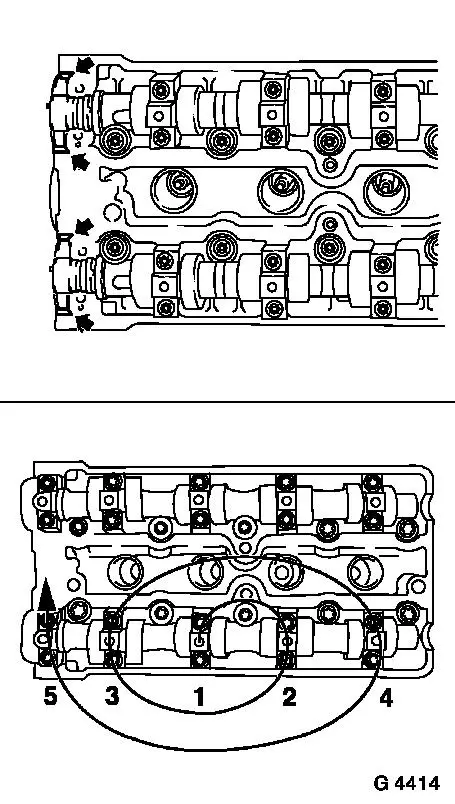
Note: Care should be
taken that the area of the front camshaft bearing caps (arrows) is
clean and free from remains of sealant
|
|
|
|
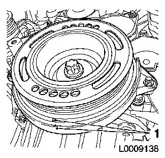
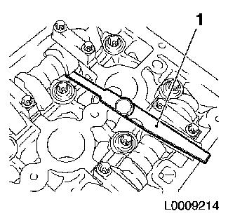
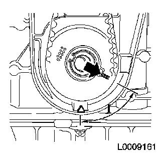
| 7. |
Set engine to TDC
| • |
Move torsional vibration damper in direction of engine rotation
to the "cylinder 1 TDC of combustion stroke position" (1)
|
|
|
|
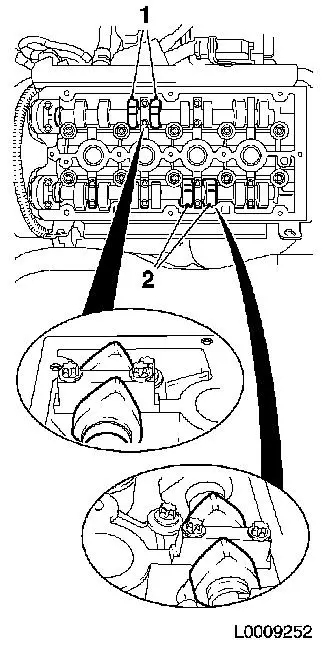
| 8. |
The cams at the intake side of cylinder 2 (1) and the exhaust
side of cylinder 3 (2) point upwards and slightly towards the
inside at the same angle
|
|
|
| 9. |
Check valve lash
| • |
Prescribed valve lash
| – |
Intake valves 0.21 - 0.29 mm (nominal value 0.25 mm)
|
| – |
Exhaust valves 0.27 - 0.35 mm (nominal value 0.30 mm)
|
|
|
| 10. |
Check 4 valves
| • |
Check valve lash with KM-6361 (1)
|
|
|
|
| 11. |
Turn crankshaft 180° in the direction of rotation of the
engine
| • |
Corresponds to 90° on the camshaft
| – |
Use the markings on the camshaft sprockets for orientation
purposes
|
|
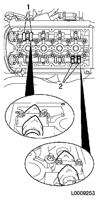
| • |
Cams on the intake side of cylinder 1 (1) and the exhaust side
of cylinder 4 (2) point upwards and slightly towards the inside at
the same angle
|
|
|
|
| 12. |
Check valve lash
| • |
Prescribed valve lash
| – |
Intake valves 0.21 - 0.29 mm (nominal value 0.25 mm)
|
| – |
Exhaust valves 0.27 - 0.35 mm (nominal value 0.30 mm)
|
|
|
| 13. |
Check 4 valves
| • |
Check valve lash with KM-6361 (1)
|
|
|
|
| 14. |
Turn crankshaft 180° in the direction of rotation of the
engine
| • |
Corresponds to 90° on the camshaft
| – |
Use the markings on the camshaft sprockets for orientation
purposes
|
|
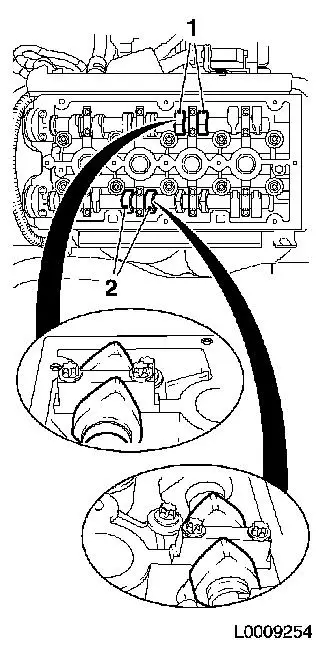
| • |
Cams on the intake side of cylinder 3 (1) and the exhaust side
of cylinder 2 (2) point upwards and slightly towards the inside at
the same angle
|
|
|
|
| 15. |
Check valve lash
| • |
Prescribed valve lash
| – |
Intake valves 0.21 - 0.29 mm (nominal value 0.25 mm)
|
| – |
Exhaust valves 0.27 - 0.35 mm (nominal value 0.30 mm)
|
|
|
| 16. |
Check 4 valves
| • |
Check valve lash with KM-6361 (1)
|
|
|
|
| 17. |
Turn crankshaft 180° in the direction of rotation of the
engine
| • |
Corresponds to 90° on the camshaft
| – |
Use the markings on the camshaft sprockets for orientation
purposes
|
|
| • |
The cams on the intake side of cylinder 4 (1) and the exhaust
side of cylinder 1 (2) point upwards and slightly towards the
inside at the same angle
|
|
|
|
| 18. |
Check valve lash
| • |
Prescribed valve lash
| – |
Intake valves 0.21 - 0.29 mm (nominal value 0.25 mm)
|
| – |
Exhaust valves 0.27 - 0.35 mm (nominal value 0.30 mm)
|
|
|
| 19. |
Check 4 valves
| • |
Check valve lash with KM-6361 (1)
|
|
|
|
| 20. |
Raise lifting platform
|
| 21. |
Remove engine splash guard (2).
| • |
Remove 2x body-bound rivets (3)
|
|
|
|
| 22. |
Set engine to 60° before TDC
| • |
Set crankshaft in direction of engine rotation to 60°
(measurement l) before TDC
|
|
|
|
| 23. |
Lower lifting platform
|
| 24. |
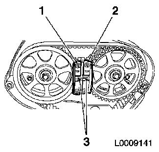
Remove toothed belt
| • |
Mark direction of rotation
|
| • |
Apply tension to toothed belt tension roller (2) in the
direction of the arrow, using an Allen key (1). Fix using KM-6333 (3)
|
|
|
|
| 25. |
Detach exhaust camshaft sprocket
| • |
Attach KM-6347 (1) in conjunction
with KM-956-1 (2) to camshaft
sprocket
| – |
Slacken 2x bolt (3) of KM-6347
|
| – |
Insert KM-6347 in the camshaft
sprocket - ensure it is correctly seated
Note: The grooves of
KM-6347 (arrows) must engage with
camshaft sprocket
|
| – |
Turn KM-6347 in the direction of the
arrow
|
|
| • |
Release bolt of camshaft sprocket (4)
|
| • |
Unscrew bolt, camshaft sprocket
| – |
Remove camshaft sprocket
|
|
|
|
|
| 26. |
Detach intake camshaft sprocket
| • |
Attach KM-6347 in conjunction with
KM-956-1 to camshaft sprocket
| – |
Slacken 2x bolt of KM-6347
|
| – |
Insert KM-6347 in the camshaft
sprocket - ensure it is correctly seated
Note: The grooves of
KM-6347 must engage in camshaft
sprocket
|
| – |
Turn KM-6347 in the direction of the
arrow
|
|
| • |
Slacken bolt of camshaft sprocket
|
| • |
Unscrew bolt, camshaft sprocket
| – |
Remove camshaft sprocket
|
|
|
| 27. |
Slacken camshaft bearing cap, exhaust camshaft
| • |
Slacken camshaft bearing caps working in spiral from outside to
inside in steps of 1/2 up to 1 turn
|
|
|
|
| 28. |
Remove exhaust camshaft
Note: Note marking on
the camshaft bearing cover with stamped numbers from 1 to 0 (there
is a dot at bottom left before each number to avoid mistakes)
| • |
Remove the camshaft bearing cover from the cylinder head and
take out the camshaft
|
|
|
|
| 29. |
Slacken camshaft bearing cap, intake camshaft
| • |
Slacken camshaft bearing caps working in spiral from outside to
inside in steps of 1/2 up to 1 turn
|
|
|
|
| 30. |
Remove intake camshaft
Note: Note marking on
the camshaft bearing cover with stamped numbers from 1 to 0 (there
is a dot at bottom left before each number to avoid mistakes)
| • |
Remove the camshaft bearing cover from the cylinder head and
take out the camshaft
|
|
|
|
| 31. |
Remove cup tappet with KM-845 (1)
|
|
|
 Install
| 32. |
Determine cup tappet size
|
Example of determining the size of a cup tappet,
intake side:
|
|
|
|
|
Dimension of fitted cup tappet
|
|
3.20 mm
|
(Identification no. 20)
|
|
Measurement between cams and cup tappets
|
+
|
0.31 mm
|
|
| |
=
|
3.51 mm
|
|
|
Required value, valve lash, intake side
|
-
|
0.25 mm
|
|
|
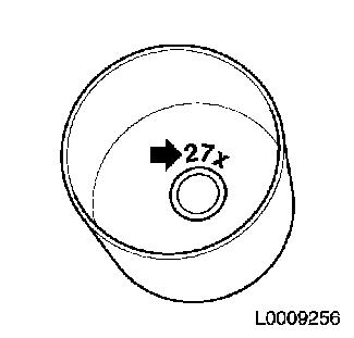
Nominal dimension of the new cup tappet
|
|
3.265 mm
|
(Identification number 27x
|
Note: The identification
number (arrow) is on the inside of the cup tappet
| • |
Now use a cup tappet with this dimension or one that is nearest
to it
|
|
|
|
| 33. |
Insert cup tappet with KM-845
| • |
Lightly coat sliding surfaces with oil
|
|
| 34. |
Install intake camshaft
| • |
Coat with MoS 2 lubricating paste
|
| • |
Insert camshaft
Note: Note the
identification marking on the camshaft bearing cover
|
| • |
Apply surface sealant to sealing surface of guide bearing
(arrows)
|
| • |
Install camshaft bearing cover
| – |
Tighten camshaft bearing caps in a spiral from the inside
outward 8 Nm
|
|
|
|
|
| 35. |
Install exhaust camshaft
| • |
Coat with MoS 2 lubricating paste
|
| • |
Insert camshaft
Note: Note the
identification marking on the camshaft bearing cover
|
| • |
Apply surface sealant to sealing surface of guide bearing
(arrows)
|
| • |
Install camshaft bearing cover
| – |
Tighten camshaft bearing caps in a spiral from the inside
outward 8 Nm
|
|
|
|
|
| 36. |
Install seal ring, exhaust camshaft
| • |
Push seal ring into camshaft bearing cover with KM-422 (1)
| – |
Use camshaft sprocket bolt (2) and washer (3)
|
|
|
|
|
| 37. |
Install seal ring, intake camshaft
| • |
Push seal ring into camshaft bearing cover with KM-422 (1)
| – |
Use camshaft sprocket bolt (2) and washer (3)
|
|
|
|
|
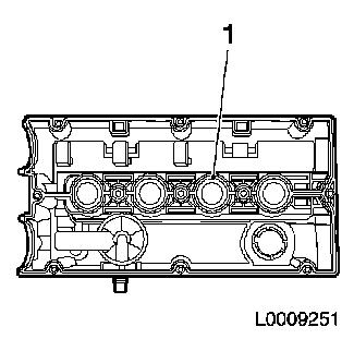
| 38. |
Replace gasket, cylinder head cover
| • |
Insert new gasket (1) in cylinder head cover
|
|
|
|
| 39. |
Remove spark plug, cylinder 1 with KM-6363
|
| 40. |
Install KM-6354 (1) in spark plug
thread, cylinder 1
|
|
|
Important: When assembling the
cylinder head cover, care must be taken that the gasket of the
cylinder head cover does not become detached. An incorrectly fitted
gasket in the cylinder head cover can cause serious damage to the
engine
|
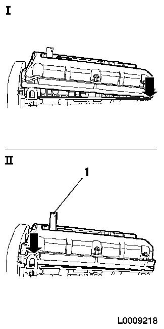
| 41. |
Place cylinder head cover in position
| • |
Lift cylinder head cover via KM-6354
|
| • |
Position cylinder head cover at the rear (i)
|
| • |
Press cylinder head cover carefully downwards at the back
(II)
|
|
|
|
| 42. |
Attach cylinder head cover
| • |
Remove adhesive tape from 3 bolts
|
| • |
Attach engine vent pipe and latch
|
|
| 43. |
Install spark plug cylinder 1 with KM-6363 25 Nm
|
| 44. |
Remove DIS-ignition module
| • |
Attach DIS ignition module cover
|
|
| 45. |
Attach KM-6347 to exhaust camshaft
sprocket
| • |
Position camshaft sprocket - note marking
|
| • |
Fit camshaft sprocket bolt (4)
| – |
Attach KM-6347 (1) in conjunction
with KM-956-1 (2) to camshaft
sprocket
|
| – |
Slacken 2x bolt (3) of KM-6347
|
| – |
Insert KM-6347 in the camshaft
sprocket - ensure it is correctly seated
Note: The grooves of
KM-6347 (arrows) must engage with
camshaft sprocket
|
| – |
Turn KM-6347 in the direction of the
arrow
|
|
|
|
|
| 46. |
Tighten outlet camshaft sprocket 50 Nm
+ 60° + 15°
|
| 47. |
Attach KM-6347 to intake camshaft
sprocket
| • |
Position camshaft sprocket - note marking
|
| • |
Screw in bolt, camshaft sprocket
| – |
Attach KM-6347 in conjunction with
KM-956-1 to camshaft sprocket
|
| – |
Slacken 2x bolt of KM-6347
|
| – |
Insert KM-6347 in the camshaft
sprocket - ensure it is correctly seated
Note: The grooves of
KM-6347 must engage in camshaft
sprocket
|
| – |
Turn KM-6347 in the direction of the
arrow
|
|
|
| 48. |
Tighten intake camshaft sprocket 50 Nm
+ 60° + 15°
|
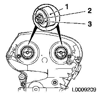
| 49. |
Lock camshaft sprockets in position with KM-6340
| • |
Position camshaft sprockets in such a way that the markings (3)
are opposite each other
|
| • |
Attach KM-6340-Left (1) to intake
camshaft sprocket
|
| • |
Insert KM-6340-Right (2)
|
|
|
|
| 50. |
Set engine to TDC
| • |
Move torsional vibration damper in direction of engine rotation
to the "cylinder 1 TDC of combustion stroke position" (1)
|
|
|
|
| 51. |
Install toothed belt
| • |
Position toothed belt
| – |
Place toothed belt on exhaust camshaft sprocket
|
| – |
Place toothed belt on intake camshaft sprocket
|
| – |
Apply tension to the toothed belt tension roller and remove
KM-6333
|
|
|
| 53. |
Turn crankshaft through 720°
| • |
2 revolutions in direction of engine rotation
|
| • |
Place toothed belt drive gear on the marking, cylinder 1 TDC of
combustion stroke (1)
|
|
|
|
| 54. |
Lock camshaft sprockets in position with KM-6340
| • |
Insert KM-6340-Left (1)
|
| • |
Insert KM-6340-Right (2)
Note: Markings (3) on
camshaft sprockets must align - otherwise dismantle toothed belt
and place in position again
|
|
|
|
Important: Ensure that it is
latched correctly
|
| 56. |
Attach front toothed belt cover (top)
|
| 57. |
| 1. |
Install air cleaner housing - Z16XEP |
| 2. |
Install air cleaner housing - Z16XE1 |
|
|
