|
Engine, Remove and Install
 Remove Remove
| 2. |
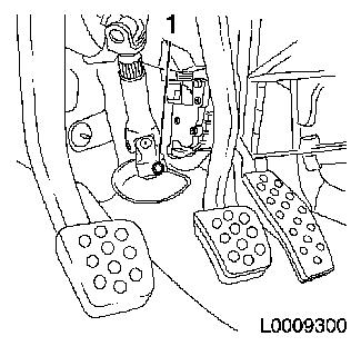
Remove steering column interim spindle
| • |
Move steering wheel to straight-ahead position
|
| • |
Remove ignition key and engage steering lock
|
|
|
|
| 3. |
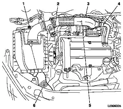
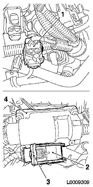
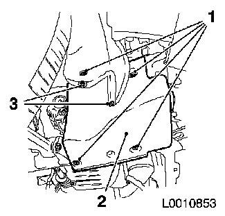
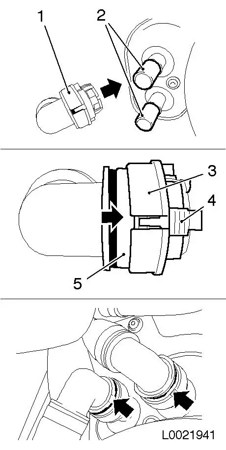
Remove air cleaner housing
| • |
Disconnect mass air flow sensor wiring harness plug (2)
|
| • |
Unclip tank vent line (3)
|
| • |
Detach engine vent hose (4) from air intake hose
|
| • |
Detach air intake hose (5) from throttle valve body
|
| • |
Detach air cleaner housing
| – |
Unclip rubber mounting at the bottom
|
| – |
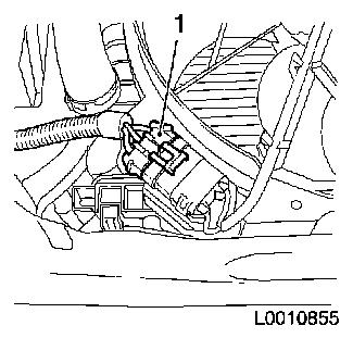
Remove air intake pipe (6)
|
|
|
|
|
| 4. |
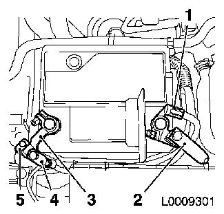
Detach earth cable
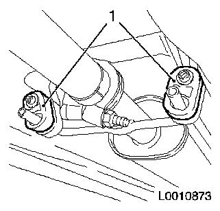
| • |
Detach earth cables (4) and (5) from earth terminal (3)
|
| • |
Detach earth connection from negative terminal
|
|
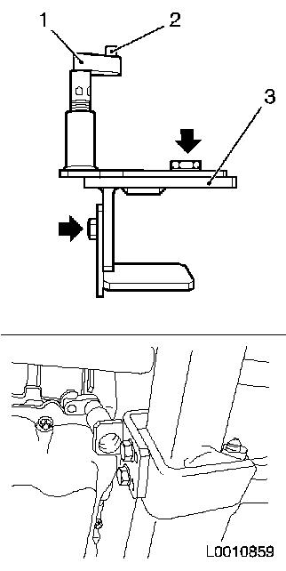
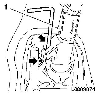
| 5. |
Detach positive cable
| • |
Detach positive cable (2) from positive terminal (1)
|
| • |
Detach positive connection from positive terminal
|
|
|
|
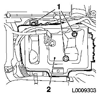
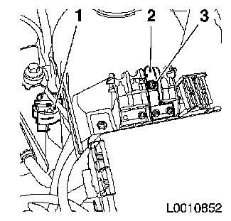
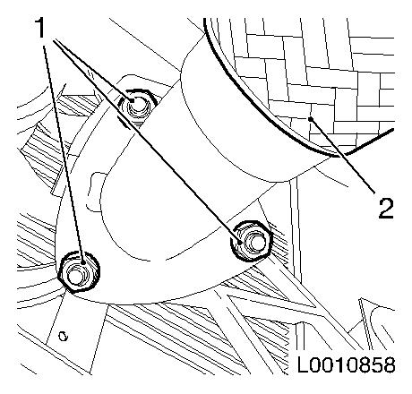
| 6. |
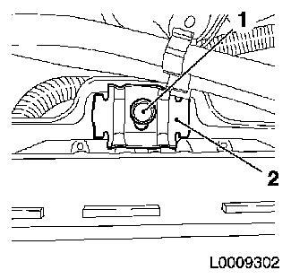
Remove battery
| • |
Unscrew bolt (1)
| – |
Remove retaining plate (2)
|
|
|
|
|
| 7. |
Remove battery support (2)
|
|
|
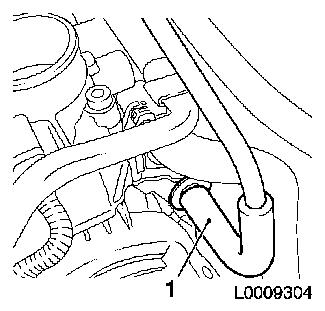
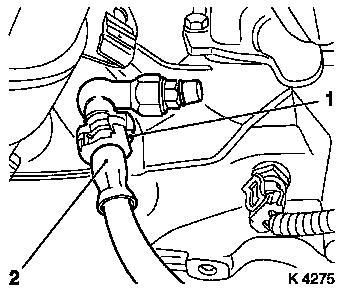
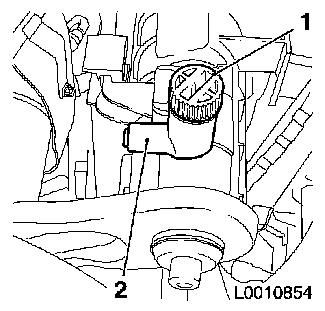
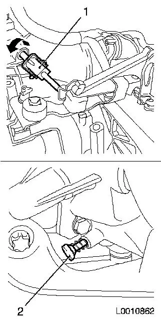
| 8. |
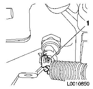
Detach tank vent valve hose (1) from tank vent valve
|
|
|
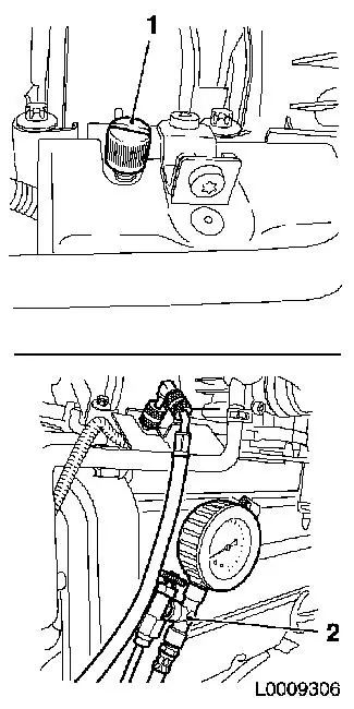
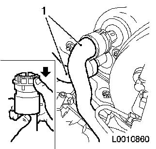
| 9. |
Release fuel pressure with KM-J-34730-91 (2) via test connection
Note: Collect exiting
fuel in a suitable container - observe safety regulations and
national legislation
| • |
Remove protective cap (1)
|
|
|
|
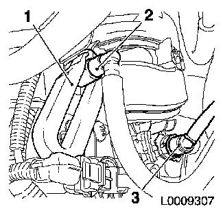
| 10. |
Detach fuel supply line (2) with KM-796 (1) from fuel distributor pipe
| • |
Disconnect quick-release fitting
|
|
| 11. |
Detach brake servo vacuum line (3) from intake manifold
| • |
Disconnect quick-release fitting
|
|
|
|
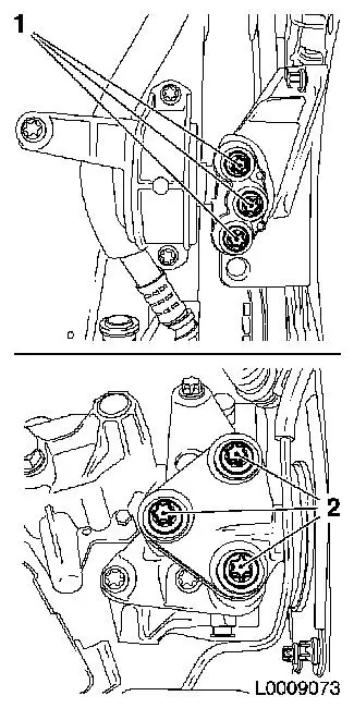
| 12. |
Disconnect engine wiring harness
| • |
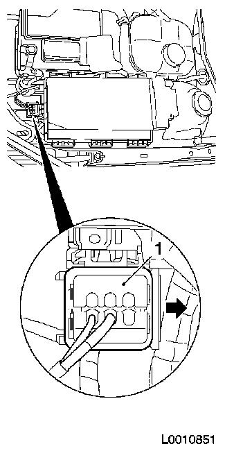
Disconnect wiring harness plug (1)
| – |
Release retainer in direction of arrow
|
|
| • |
Disconnect wiring harness plugs (2) from engine control unit
(4)
|
| • |
Unclip 3x wiring harnesses
|
|
|
|
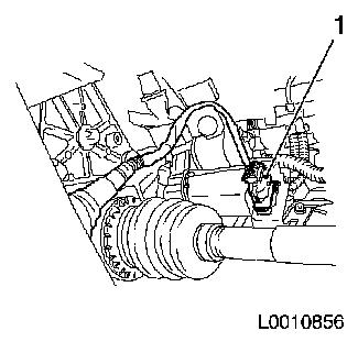
| 13. |
Disconnect wiring harness plug (1), reversing light switch
|
|
|
| 14. |
Disconnect wiring harness plug, earth connection (1)
| • |
Release retainer in direction of arrow
|
|
|
|
| 15. |
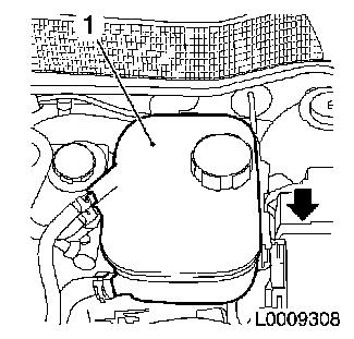
Remove coolant expansion tank (1)
| • |
Pull out of bracket in direction of arrow
|
|
|
|
| 16. |
Disconnect steering wiring harness
| • |
Remove fuse carrier cover
|
| • |
Detach positive cable (2) from fuse carrier
|
| • |
Disconnect wiring harness plug (1)
|
| • |
Expose wiring harness
| – |
Unclip 3x wiring harnesses
|
|
|
|
|
| 17. |
Detach pressure hose, central release (2)
| • |
Place collecting pan underneath.
|
| • |
Unlatch retaining clamp (1) with screwdriver and detach
|
| • |
Bend clip together a little and insert back into connecting
piece
|
| • |
Tie up pressure line for central release
|
|
|
|
| 19. |
Raise vehicle by half its height
|
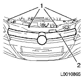
| 21. |
Remove radiator grille
| • |
Remove 4x body-bound rivets (1)
|
| • |
Unclip radiator grille (2) upwards from front panelling
|
|
|
|
| 22. |
Raise vehicle by half its height
|
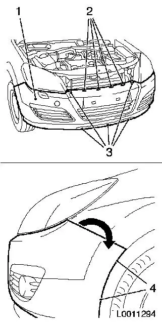
| 23. |
Undo front panelling (1)
| • |
Remove 5x body-bound rivets (3)
|
|
| 24. |
Remove front panelling
Note: Second man
| • |
Push front panelling upwards in direction of arrow and pull out
of bracket
|
| • |
Unclip outside temperature sensor
|
|
|
|
| 25. |
Remove right engine splash guard (2)
| • |
Remove 2x body-bound rivets (3)
|
|
|
|
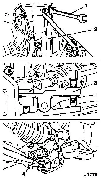
| 26. |
Detach swing arm (2) from spring strut support tube
| • |
Unscrew 2x nuts
Note: Use spanner (1)
to hold against flat surface
|
|
| 27. |
Detach tie rods from steering knuckle with KM-507-C (3)
|
| 28. |
Detach guide joints (4) from steering knuckle
| • |
Expand steering knuckle bolts with KM-915
|
| • |
Pull guide joints out of steering knuckle
|
|
|
|
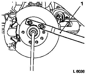
| 29. |
Remove axle shafts from wheel hub
| • |
Unscrew 2x nuts
| – |
Counterhold at wheel hub with KM-468-B (1)
|
|
|
|
|
| 30. |
Raise vehicle by half its height
|
| 31. |
Drain coolant
| • |
Place collecting pan underneath.
|
| • |
Attach suitable hose to drain connection (2)
|
| • |
Open coolant drain screw (1)
|
| • |
Close coolant drain screw
|
|
|
|
| 32. |
Disconnect cooling module wiring harness plug (1)
|
|
|
| 33. |
Disconnect wiring harness plug of catalytic converter control
oxygen sensor (1)
|
|
|
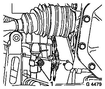
| 34. |
Detach clamp (1) from shift rod
| • |
Detach shift guide from shift rod
|
|
|
|
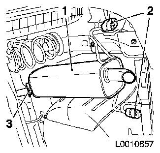
| 35. |
Remove end silencer (1)
| • |
Slacken fastening clamp (3)
|
| • |
Remove from bracket
| – |
Detach 2x rubber bearings (2)
|
|
| • |
Detach end silencer from front silencer
Note: Second man
|
|
|
|
| 36. |
Detach front exhaust pipe (2) from catalytic converter
|
|
|
| 37. |
Remove front exhaust pipe with front silencer
| • |
Unhook 2x rubber bearing (1)
|
|
|
|
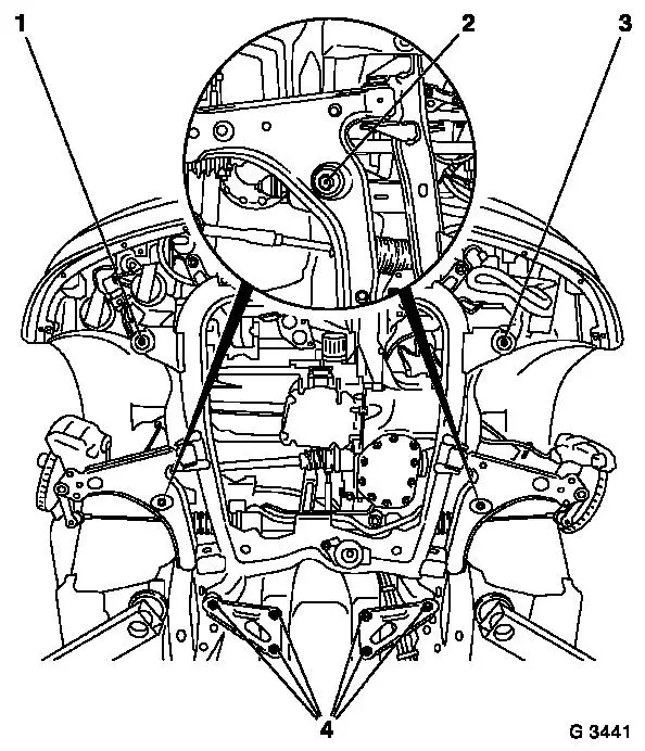
| 38. |
Insert KM-6173 (3)
| • |
Slacken 4x bolts (arrows) and hand-tighten
|
| • |
Align KM-6173 at front axle body
|
| • |
Wind up the support bearing (1)
| – |
Journal (2) must sit in mount at cylinder block
|
|
|
|
|
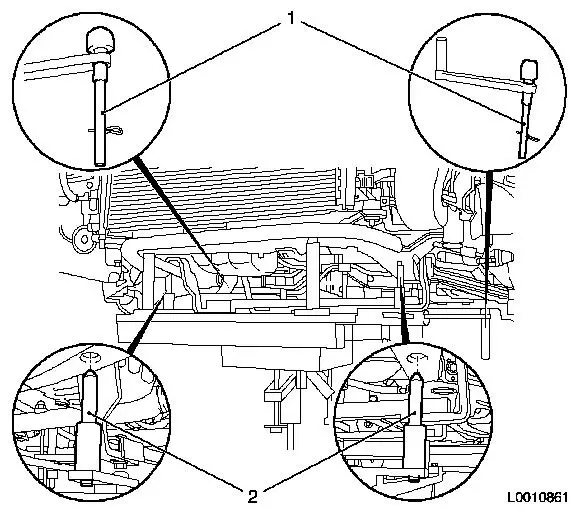
| 39. |
Attach KM-6001-A (1)
Note: Attaching KM-6001-A guarantees perfect alignment of the
drive unit with the front axle body
| • |
Slacken 3x bolts (arrows) in adjusting rails
|
| • |
Insert KM-6001-A
| – |
The journals (2) and (5) must sit in the guide holes of the
front axle body
|
|
| • |
Tighten 3x bolts in adjusting rails
|
| • |
Adjust support bearings, front (4) and rear (3)
| – |
Raise support bearings up to the stop on the guide journals
Note: The guide
journals must be seated free from play in the support bearings
|
|
|
|
|
| 40. |
Lower vehicle by its full height
|
| 41. |
Detach coolant hoses (1) from heater core
Note: Mark assignment
using coloured markings
| • |
Place collecting pan underneath.
|
| • |
Release 2x quick-release fittings in direction of arrow
|
|
|
|
| 42. |
Detach right engine damping block from engine damping block
bracket
|
| 43. |
Detach left engine damping block from engine damping block
bracket
|
|
|
| 44. |
Raise vehicle by its full height
|
| 45. |
Attach KM-904 with KM-6390
| • |
Attach to hydraulic lifter
Note: Use hydraulic
jack that can be lowered to a height of at least 100 cm
|
| • |
Lower centring pins (1)
|
| • |
Place under front axle body, ensure there is no play
| – |
Centring pins (2) must engage in the relevant holes in the
front axle body
|
|
|
|
|
Important: It is not permissible
to disassemble the front axle body with an impulse or impact
screwdriver
|
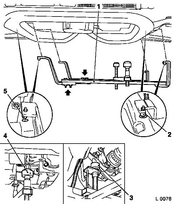
| 46. |
Remove front axle body
| • |
Unscrew 10x bolts (1, 2, 3, 4)
Note: Note different
bolt lengths
|
|
|
|
Important: Ensure that no
attached parts are damaged
|
| 47. |
Move out front axle body
Note: 2 people
|
 Install
| 48. |
Check thread
| • |
Check ease of movement of 10x cage nuts, replacing if
necessary
|
|
| 49. |
Lock shift rod
| • |
Turn shift rod (1) in the direction of the arrow
|
| • |
At the same time, cause the locking pin (2) to engage by
pressing it
|
|
|
|
Important: Ensure that no
attached parts are damaged
|
| 50. |
Move front axle body back in
Note: 2 people
|
Important: It is not permissible
to assemble the front axle body with an impulse or impact
screwdriver
|
| 51. |
Fit front axle body
| • |
Tighten 10x bolt 90 Nm + 45° +
15°
|
|
| 52. |
Detach KM-904 and KM-6390
|
| 53. |
Lower vehicle by its full height
|
| 54. |
Attach right engine damping block to engine damping block
adapter
|
| 55. |
Attach left engine damping block to engine damping block
adapter
|
Important: It is imperative to
adhere to the following assembly order
|
| 56. |
Attach coolant hoses to heater core
| • |
Fit 2x quick release fittings (1) onto heater core connection
port (2) as far as they will go
Note: Pay attention to
coloured markings
|
| • |
Slide the 2x quick-release fitting catches (3) in the direction
of the arrow all the way to the stop by simultaneously pressing the
release buttons (4)
| – |
The colour rings (5) must be visible
|
|
| • |
Check that quick release fittings are correctly seated and that
the colour rings (5) are visible
|
|
|
|
| 57. |
Raise vehicle by half its height
|
| 58. |
Install axle shafts in wheel hub
| • |
Insert guiding joint into steering knuckle
|
| • |
Tighten 2x nut 150 Nm , slacken
45° , then tighten to 250 Nm
|
| • |
Counterhold at wheel hub with KM-468-B
|
|
| 59. |
Attach guide joint to steering knuckle
| • |
Use new nuts
| – |
Tighten 2x screwed joint 50 Nm
|
|
|
| 60. |
Attach tie rods to steering knuckle
| • |
Tighten 2x nut 30 Nm + 90° +
15°
|
|
| 61. |
Attach swing arm to spring strut support tube
| • |
Tighten 2x nut 65 Nm
| – |
Use spanner to counterhold against flat surface
|
|
|
| 62. |
Raise vehicle by half its height
|
| 65. |
Insert front exhaust pipe with front silencer
Note: Second man
| • |
Attach 2x rubber bearings
|
|
| 66. |
Attach front exhaust pipe with front silencer to catalytic
converter
|
| 67. |
Install rear silencer
Note: Second man
| • |
Fit rear silencer to front silencer
|
| • |
Attach 2x rubber bearings
|
|
| 68. |
Connect wiring harness plug for catalytic converter control
oxygen sensor
|
| 69. |
Attach wiring harness plug for cooling module
|
| 70. |
Attach right engine splash guard
| • |
Install 2x body-bound rivets
|
|
| 71. |
Attach oil drain bolt to oil pan
| • |
Tighten drain bolt 10 Nm
|
|
| 72. |
Fit front panelling
| • |
Second man
Note: Slide side front
panelling into bracket
|
| • |
Clip in outside temperature sensor
|
| • |
Install 5x body-bound rivets
|
|
| 73. |
Install radiator grille
| • |
Clip into front panelling
|
| • |
Install 4x body-bound rivets
|
|
| 76. |
Attach pressure line for central release
|
| 77. |
Connect steering wiring harness
| • |
Attach positive cable to fuse carrier
|
| • |
Fix wiring harness plug
|
|
| 78. |
Insert coolant expansion tank into bracket
|
| 79. |
Attach earth cable to earth terminal
| • |
Connect one wiring harness plug
|
|
| 80. |
Attach positive cable to positive terminal
|
| 81. |
Connect engine wiring harness
| • |
Connect wiring harness plug to engine control unit
|
| • |
Attach wiring harness plug to reversing light switch
|
| • |
Connect wiring harness plug, engine wiring harness
|
|
| 82. |
Attach brake servo vacuum line to intake manifold
|
| 83. |
Attach fuel supply line to fuel rail
| • |
Connect quick release fitting
|
|
| 84. |
Attach vent hose to tank vent valve
|
| 85. |
Insert shift lever fixing KM-527-A
(1) in shift lever housing
| • |
Unclip cover of central console
|
| • |
Detach shift lever cover from central console
|
|
|
|
| 86. |
Raise vehicle by its full height
|
| 87. |
Attach shift guide clamp to shift rod
| • |
Tighten bolt 12 Nm + 180° to
225°
|
|
| 88. |
Lower vehicle by its full height
|
| 89. |
Vent hydraulic clutch actuator 
|
| 90. |
Install battery holder
| • |
Attach wiring harness to battery support
|
|
| 91. |
Install air cleaner housing
| • |
Attach air cleaner housing to wheelhouse
|
| • |
Attach air intake hose to throttle valve module
|
| • |
Attach engine vent hose to timing case
|
| • |
Attach wiring harness plug to hot film mass air flow meter
|
|
| 92. |
Install battery
| • |
Install battery bracket
|
| • |
Attach positive connection to positive terminal
|
| • |
Attach earth connector to negative terminal
|
|
| 93. |
Tighten bolt, intermediate steering spindle 22 Nm
| • |
Coat bolt with screw locking compound and insert
|
|
| 94. |
Remove shift lever fixing
Note: Locking pin in
adjusting bore releases itself the first time the shift lever is
engaged in the direction "R"
| • |
Draw KM-527-A out of shift lever
housing
|
| • |
Clip shift lever cover into central console
|
|
| 95. |
Check that gears shift correctly
| • |
Check ease with which gear changes are made with the vehicle
stationary, the engine running and the clutch disengaged
|
|
| 96. |
Fill with coolant and bleed
|
| 97. |
Program volatile memories
|
|
