|
Repair Engine Using An Engine Short Block
(Z16XEP)
 Remove Remove
| 2. |
Remove transmission from engine
| 1. |
Manual transmission  |
| 2. |
MTA manual transmission |
|
| 3. |
Place collecting basin underneath.
|
| 4. |
Drain engine oil
| • |
Tighten drain bolt 14 Nm
|
|
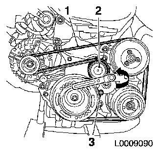
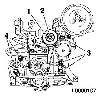
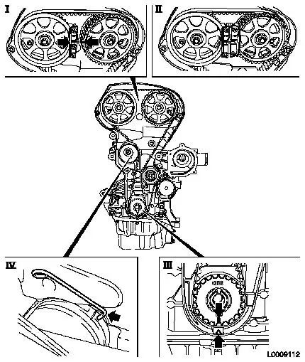
| 5. |
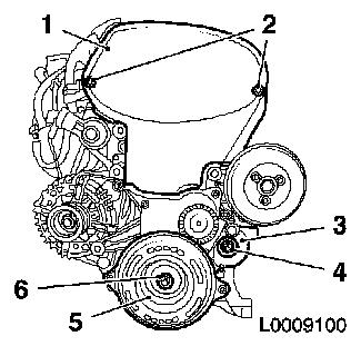
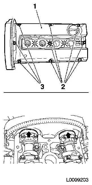
Detach ribbed V-belt (1)
| • |
Mark direction of rotation
|
| • |
Apply tension to ribbed V-belt tensioner (2) in the direction
of the arrow and fix with KM-6130 (3)
|
|
|
|
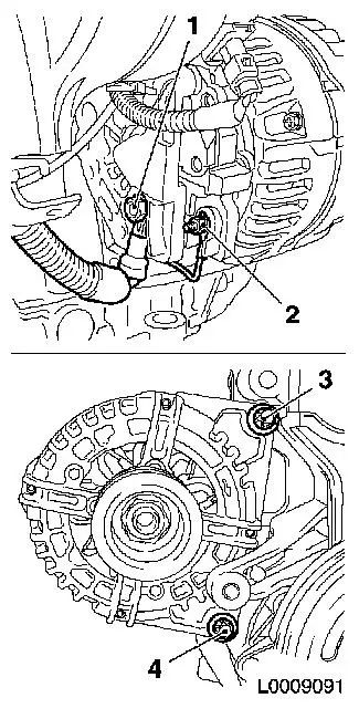
| 6. |
Detach alternator
| • |
Disconnect alternator from power supply
| – |
Unscrew 2x nuts (1) and (2)
|
|
| • |
Unscrew 2x bolts (3) and (4)
|
|
|
|
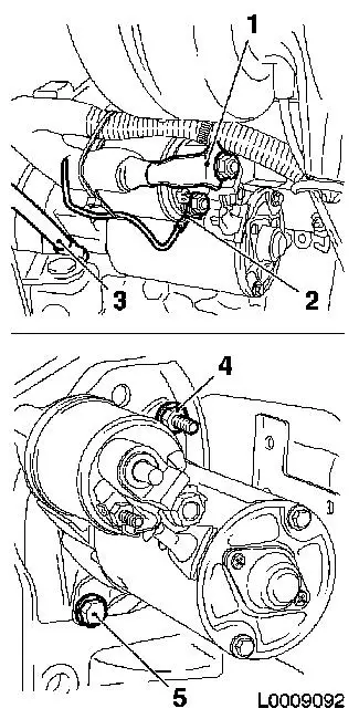
| 7. |
Detach starter
| • |
Detach cable (1) and (2)
|
| • |
Disconnect earth cable (3)
|
| • |
Unscrew 2x fastening bolt (4) and (5)
|
|
|
|
| 8. |
Detach intake manifold support
|
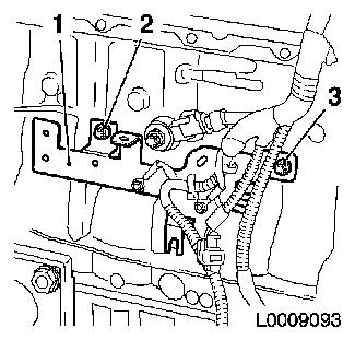
| 9. |
Detach wiring harness bracket (1) from cylinder block
| • |
Unscrew 2x bolts (2) and (3)
|
|
|
|
| 10. |
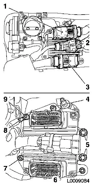
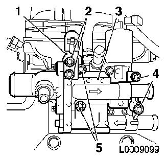
Detach engine control unit with engine control unit bracket
from intake manifold
| • |
Wiring harness plugs, engine control unit (1) and (3)
| – |
Unlatch in direction of arrow and disconnect
|
|
| • |
Disconnect wiring harness plug (2)
|
| • |
Detach bracket for wiring harness plug
|
| • |
Unscrew 3x fastening bolt (4), (6) and (7)
|
|
|
|
| 11. |
Detach engine wiring harness
| • |
Disconnect 17x wiring harness plugs
|
| • |
Unclip wiring harness from brackets and expose
|
|
| 12. |
Remove oil dipstick guide tube (old design)
|
| 13. |
Remove oil dipstick guide tube (new design)
|
| 14. |
Detach engine transport shackle, intake side
|
| 15. |
Detach engine transport shackle, exhaust side
|
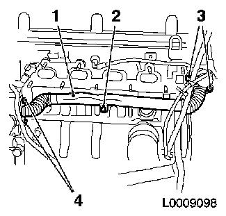
| 16. |
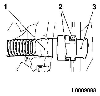
Detach engine vent pipe (1) from cylinder head cover (3)
|
|
|
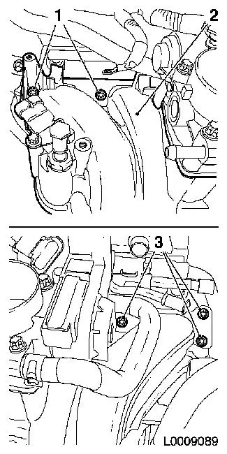
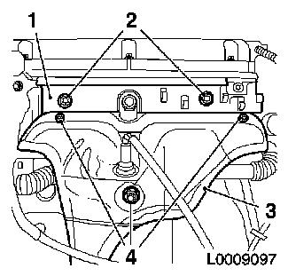
| 17. |
Detach intake manifold (2) from cylinder head
| • |
Detach coolant hose from coolant flange.
|
| • |
Detach vacuum hose from intake manifold
|
| • |
Unscrew 2x bolts (1) and (3)
|
|
|
|
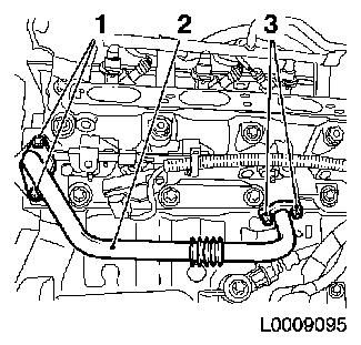
| 18. |
Detach exhaust gas recirculation metal tube (2)
| • |
Unscrew 4x bolt (1) and (3)
|
|
|
|
| 19. |
Detach intake manifold flange (1)
|
|
|
| 20. |
If present: detach wiring harness bracket (1) from cylinder
head
|
| 21. |
Detach turbocharger (3) from exhaust manifold
|
|
|
| 22. |
Detach exhaust manifold (2)
| • |
Detach catalytic converter support from engine block
|
|
|
|
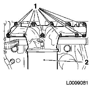
| 23. |
Remove coolant pipe (1)
| • |
Unscrew 5x bolts (2), (3) and (4)
|
|
|
|
| 24. |
Detach coolant flange (3)
| • |
Unscrew 4x bolts (4) and (5)
|
|
|
|
| 26. |
Remove ribbed V-belt tensioner (3)
Note: Ribbed V-belt
tensioner remains locked with KM-6130
|
| 27. |
Detach toothed belt cover (top) (1)
|
| 28. |
Detach incremental disc (5)
|
|
|
| 29. |
Detach lower part of toothed belt cover (7)
|
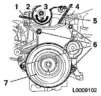
| 30. |
Stop toothed belt tensioner
| • |
Apply tension in the direction of the arrow with an Allen key
(1) and lock with KM-6333 (4)
|
|
| 31. |
Remove toothed belt (5)
| • |
Mark direction of rotation
|
|
| 32. |
Detach toothed belt tensioner (2)
|
|
|
| 33. |
Detach right engine damping block support
|
| 34. |
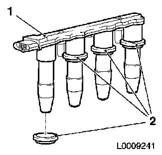
Remove DIS-ignition module
| • |
Remove cover of DIS-ignition module in the direction of the
arrow
Note: Note arrow on
cover
|
| • |
Remove from spark plugs using KM-6009
(1)
|
|
|
|
| 35. |
Detach cylinder head cover (1)
| • |
Unlatch and remove engine vent pipe
|
| • |
Slacken 3x bolt (3) pull upwards and fix in this position with
adhesive tape
|
| • |
Slacken 6x bolts (2)
Note: Care should be
taken that the area of the front camshaft bearing caps (arrows) is
clean and free from remains of sealant
|
|
|
|
Important: Remove cylinder head
only when engine is cold (room temperature)
|
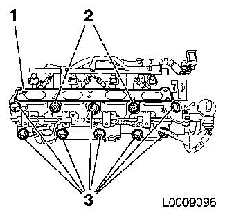
| 36. |
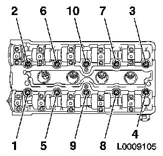
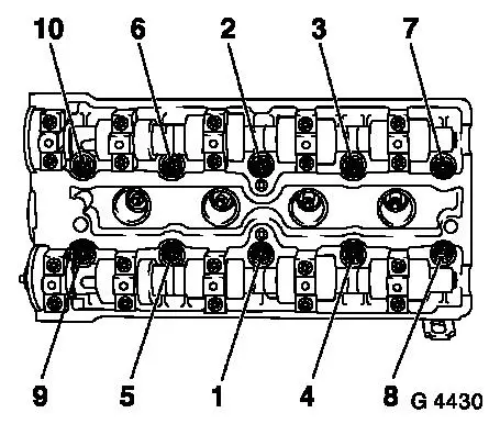
Remove cylinder head
| • |
Unscrew 10x bolt
Note: Unfasten bolts in
the order shown
|
|
|
|
| 37. |
Remove cylinder head
Note: Second
mechanic
| • |
Lay cylinder head on suitable base
|
| • |
Remove cylinder head gasket
|
|
Important: Remove gasket residue
and clean sealing surfaces. Do not use sharp metal tools. Take care
not to damage the sealing surfaces of the cylinder head
|
| 38. |
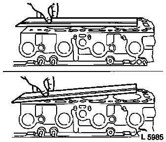
Check for plane surface
| • |
Use a straight edge to check the cylinder head and cylinder
block lengthwise, widthwise and diagonally for distortion
|
|
|
|
| 39. |
Remove cylinder head
Note: Second
mechanic
| • |
Lay cylinder head on suitable base
|
| • |
Remove cylinder head gasket
|
|
| 40. |
Detach thrust plate and clutch disk
|
| 42. |
Release flywheel lock
|
| 43. |
Rotate engine on engine overhaul stands through 180°
|
| 44. |
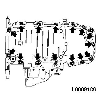
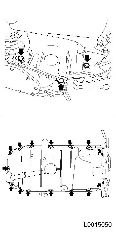
Possibility 1: Remove oil pan (old design)
| • |
Unscrew 3x bolt from transmission
|
| • |
Unscrew 15x bolts (arrows)
|
|
|
|
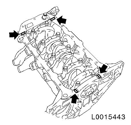
| 45. |
Possibility 2: Release oil pan (new design)
| • |
Remove 3x bolt (arrows) from transmission
|
| • |
Remove 15x bolts (arrows) from engine block
|
|
|
|
| 46. |
Detach toothed belt guide roller (1)
|
| 47. |
Remove pump module
| • |
Unscrew 8x bolts (3) and (4)
Note: Note different
screw lengths
|
|
|
|
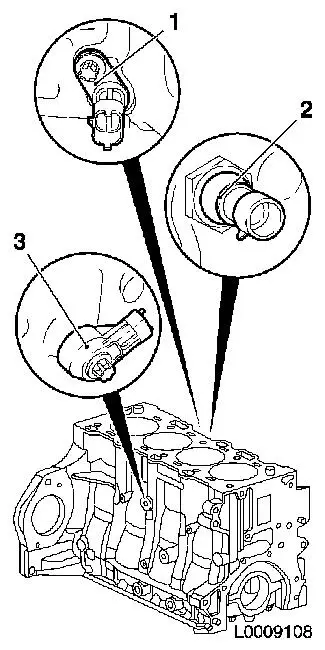
| 48. |
Detach knock sensor (3)
|
| 49. |
Detach oil pressure switch (2)
|
| 50. |
Remove crankshaft sensor (1)
|
|
|
 Install
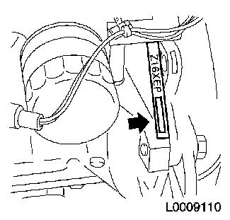
| 51. |
Emboss engine number
| • |
Onto flattened area on cylinder block (arrow) with numbers
punches
|
|
|
|
| 52. |
Clean sealing surfaces.
|
| 54. |
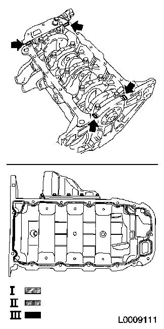
Possibility 1 (old design oil pan), apply liquid sealant
Note: The assembly time
including torque check must take no longer than 10 min
| • |
Apply an approx. 2 mm thick bead of silicone sealing compound
to the joints (arrows)
|
| • |
Apply a bead of silicone sealing compound approx. 2.5 mm thick
(dimension I) and in the area of the rear crankshaft bearing cap a
bead approx. 3.5 mm thick (dimension II)
|
| • |
In addition, apply a bead of silicone sealing compound approx.
3 mm thick (dimension III) to the oil intake pipe connection and
the two oil return lines
|
|
|
|
| 55. |
Possibility 2 (oil pan, new design): Apply a bead of silicone
sealant approximately 3.5 mm thick to the joint surfaces (arrows)
of the oil pan
|
|
|
|
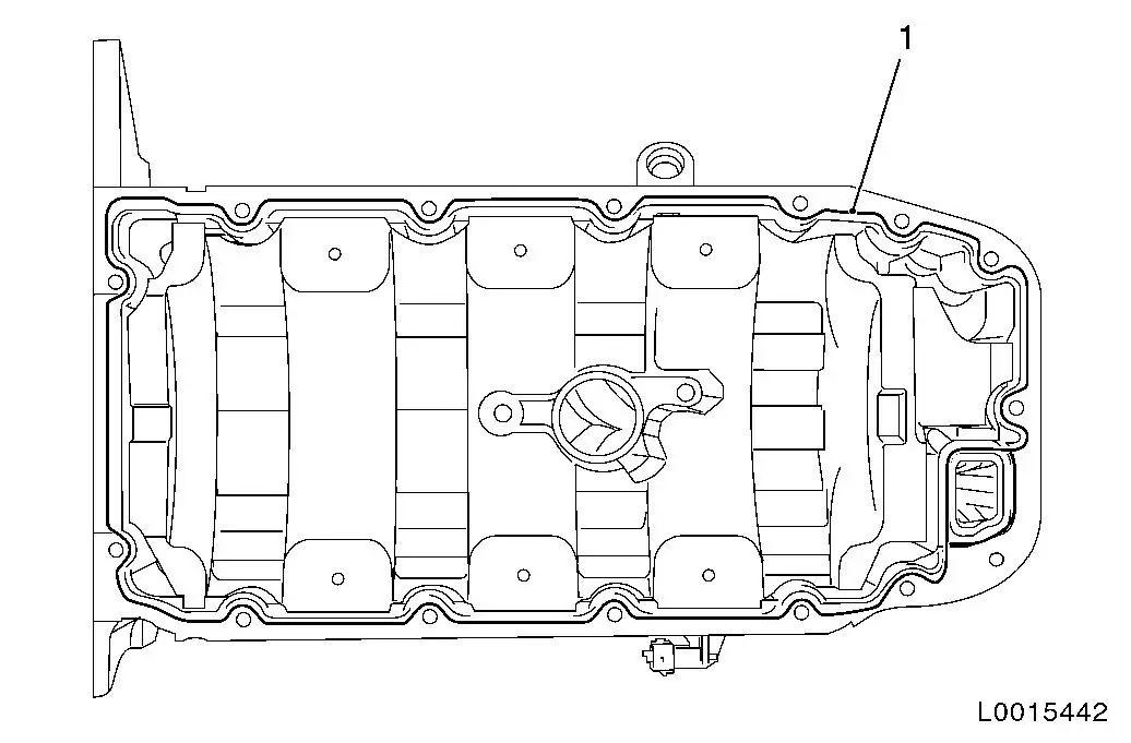
| 56. |
Possibility 2 (oil pan, new design): Apply oil pan sealant to
oil pan
Note: The assembly time
including torque check must take no longer than 10 min
| • |
Apply an approx. 3.5 mm thick bead of oil pan sealant (1) as
illustrated
|
|
|
| 57. |
Install oil pan
| • |
Tighten 15x bolt on cylinder block and pump module 10 Nm
|
| • |
Tighten 3x bolt on transmission 40
Nm
|
| • |
For old design oil pan: insert 2x rubber plug
|
|
| 58. |
Attach crankshaft sensor 8 Nm
|
| 59. |
Attach knock sensor 20 Nm
|
| 60. |
Attach oil pressure switch 20 Nm
|
| 61. |
Install pump module
| • |
Replace gasket
Note: Note different
screw lengths
|
|
| 62. |
Insert toothed belt guide roller
| • |
Tighten bolt 20 Nm + 120° +
15°
|
|
| 63. |
Fit flywheel
| • |
Tighten 6x bolt 35 Nm + 30° +
15°
| – |
Apply screw locking compound
|
|
|
| 64. |
Attach thrust plate and clutch disk
|
Important: Remove gasket residue
and clean sealing surfaces. Do not use sharp metal tools. Take care
not to damage the sealing surfaces of the cylinder head
|
| 65. |
Check for plane surface
| • |
Use a straight edge to check the cylinder block and cylinder
head lengthwise, widthwise and diagonally for distortion
|
|
|
|
| 66. |
Position cylinder head
| • |
Install cylinder head gasket
Note: Second
mechanic
|
Important: Check installation
position
|
| • |
Position cylinder head
|
|
| 67. |
Install cylinder head
| • |
Tighten 10x bolt 25 Nm + 90° +
90° + 90° + 45°
Note: Note correct
tightening sequence
| – |
Use new cylinder head bolts
|
|
|
|
|
| 68. |
Attach toothed belt tensioner
| • |
Tighten bolt 20 Nm + 120° +
15°
|
|
| 69. |
Set crankshaft to cylinder 1 TDC of combustion stroke
| • |
Marking on toothed belt drive gear and timing case
|
|
| 70. |
Position toothed belt
| • |
Move crankshaft in direction of engine rotation to "cylinder 1
TDC of combustion stroke" (III)
|
| • |
Position camshaft sprockets in such a way that the markings
(arrows) are opposite each other
|
| • |
Attach KM-6340-Left to intake
camshaft sprocket (I)
|
| • |
Insert KM-6340-Right (II)
|
| • |
Lock toothed belt tensioner with KM-6333 (IV)
|
| • |
Position toothed belt
| – |
Note direction of travel
|
|
|
| 71. |
Timing, Check
| • |
Move crankshaft by two revolutions (720°) in direction of
engine rotation to "Cylinder 1 TDC of combustion stroke" mark
(III)
|
| • |
Markings on the camshaft sprockets must be exactly opposite
each other (I)
|
|
|
|
| 72. |
Check valve lash and adjust if necessary
|
| 73. |
Attach toothed belt cover at the bottom
|
| 74. |
Fit torsional vibration damper
Important: Use new bolt
|
| • |
Lock flywheel with KM-911 or KM-6625
|
| • |
Tighten bolt 95 Nm + 45° +
15°
|
|
| 75. |
Attach ribbed V-belt tensioner
|
| 76. |
Attach right engine damping block support
|
| 77. |
Attach coolant flange
|
| 78. |
Attach wiring harness bracket to coolant flange
|
| 80. |
Attach exhaust manifold
|
| 81. |
Attach catalytic converter support to catalytic converter
|
| 82. |
Attach heat shield to exhaust manifold
|
| 83. |
Install oil dipstick guide tube (old design)
|
| 84. |
Install oil dipstick guide tube (new design)
|
| 85. |
Attach intake manifold flange
| • |
Connect wiring harness plug, injectors
|
| • |
Connect wiring harness plug, PDA system vacuum unit
|
|
| 86. |
Attach exhaust gas recirculation metal tube
|
| 87. |
Install intake manifold
| • |
Attach vacuum hose to vacuum unit of PDA system
|
| • |
Attach coolant hose to thermostat module
|
|
| 88. |
Install intake manifold support
| • |
Fasten to cylinder block
|
| • |
Attach to intake manifold
|
|
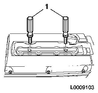
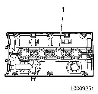
| 89. |
Replace gasket, cylinder head cover
| • |
Insert new gasket (1) in cylinder head cover
|
|
|
|
| 90. |
Remove spark plug, cylinder 1
|
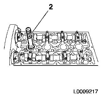
| 91. |
Install KM-6354
| • |
Install KM-6354 (1)
| – |
in spark plug thread, cylinder 1
|
|
|
|
|
Important: When assembling the
cylinder head cover, care must be taken that the gasket of the
cylinder head cover does not become detached. An incorrectly fitted
gasket in the cylinder head cover can cause serious damage to the
engine
|
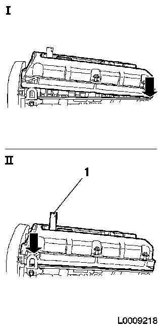
| 92. |
Place cylinder head cover in position
| • |
Lift cylinder head cover via KM-6354
|
| • |
Position cylinder head cover at the rear (i)
|
| • |
Press cylinder head cover carefully downwards at the back
(II)
|
|
|
|
| 93. |
Attach cylinder head cover
| • |
Remove adhesive tape from 3 bolts
|
| • |
Attach engine vent pipe and latch
|
|
| 94. |
Install spark plug, cylinder 1
| • |
using KM-6363
| – |
Tightening torque 25 Nm
|
|
|
| 95. |
Attach DIS-ignition module (1)
| • |
Attach DIS ignition module cover
|
|
|
|
| 96. |
Attach engine transport shackle, exhaust side
|
| 97. |
Attach engine transport shackle, intake side
|
| 98. |
Attach engine wiring loom
| • |
Attach wiring harness to rear toothed belt cover
|
| • |
Attach 9x wiring harness plug for camshaft sensor, cylinder
block oil pressure sensor, cylinder head oil pressure sensor,
crankshaft pulse pick-up, thermostat heating, coolant temperature
sensor, EGR valve, knock sensor, engine oil level sensor
|
|
| 99. |
Attach wiring harness bracket to cylinder block
|
| 102. |
Attach engine control unit bracket with engine control unit
| • |
Connect and lock engine control unit wiring harness plug
|
|
| 103. |
Clip engine wiring harness to bracket
|
| 104. |
Attach earth cable to engine control unit support
|
| 105. |
Attach wiring harness bracket to cylinder head
|
| 106. |
Insert ribbed V-belt
Note: Observe direction
of rotation
| • |
Apply tension to ribbed V-belt tensioner (2) in the direction
of the arrow (anti-clockwise) and place ribbed V-belt in position
(1)
|
|
|
|
| 107. |
Attach toothed belt cover upper section
|
| 108. |
Attach transmission to engine
| 1. |
Manual transmission |
| 2. |
MTA manual transmission |
|
| 110. |
Top up engine oil.
| • |
Check engine oil level and top up if necessary
|
|
|
