|
One Injector, Remove and Install
Important: When
working on the fuel system it is essential to pay attention to
cleanliness as even the smallest dirt particles can lead to faults
in engine operation or in the fuel system. Open fuel connections
must be sealed with appropriate plugs from the Opel Parts Catalogue
(catalogue number: 45 06 154 / part number: 9201697). Sealing plugs
are only intended to be used once.
 Remove Remove
| 2. |
Disconnect battery
| • |
Detach earth connection from earth terminal
|
|
| 3. |
Raise vehicle by its full height
|
| 4. |
Detach the lower engine cover and right engine splash guard
|
| 5. |
Place collecting basin underneath.
|
| 6. |
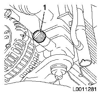
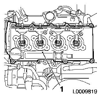
Drain coolant
| • |
Open drain bolt on radiator (1)
|
|
|
|
| 7. |
Attach the lower engine cover and right engine splash guard
|
| 8. |
Lower vehicle by its full height
|
| 9. |
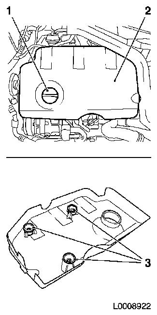
Remove engine cover (2)
| • |
Detach oil filler port closure cap (1)
|
| • |
Pull off engine cover
Note: Rubber retainers
(3) must remain on engine cover
|
| • |
Attach oil filler port closure cap
|
|
|
|
| 10. |
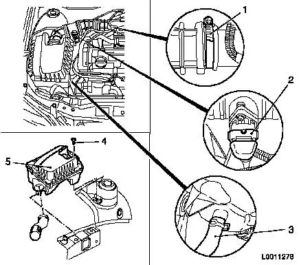
Remove air cleaner housing (5) with air intake hose
| • |
Detach wiring harness plug (2) from hot film mass air flow
meter
|
| • |
Detach air intake hose from air intake pipe
|
| • |
Detach air cleaner housing from wheel housing
|
| • |
Detach water drain hose (3) from air cleaner housing
|
|
|
|
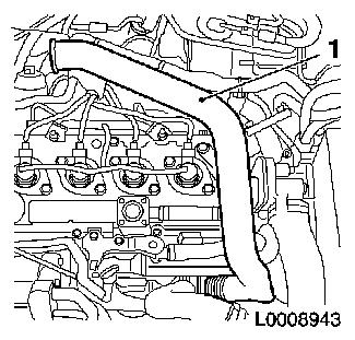
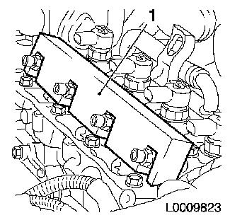
| 11. |
Remove air intake manifold (1)
|
|
|
| 12. |
Remove charge air pipe (1)
|
|
|
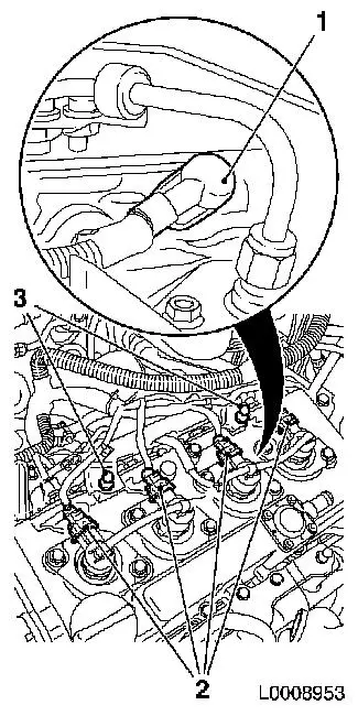
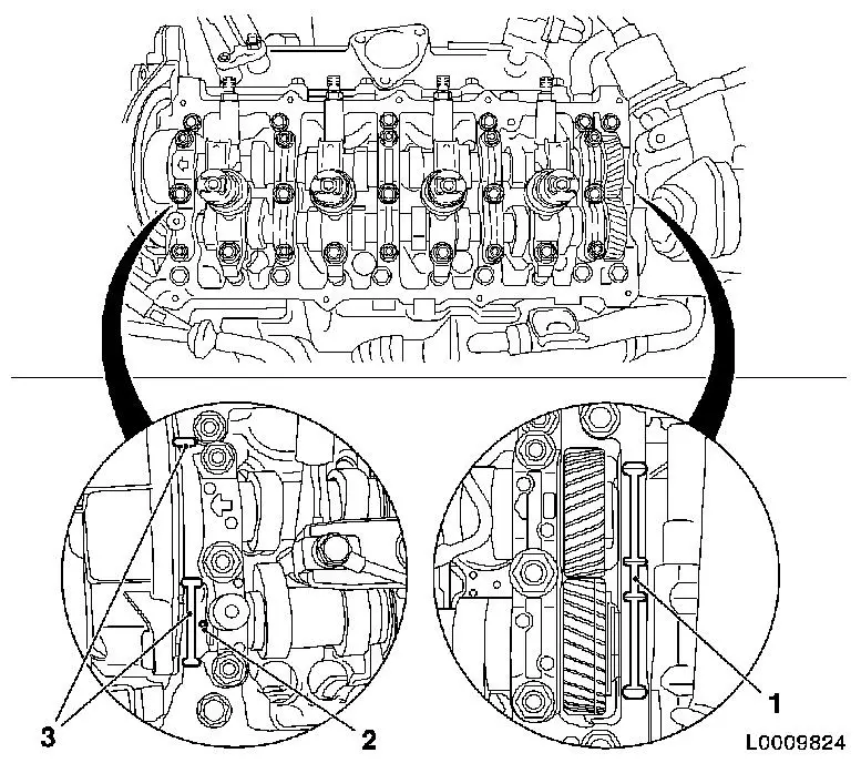
| 13. |
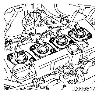
Detach wiring harness for injectors
| • |
Disconnect 4x wiring harness plugs for injector (2)
|
| • |
Disconnect 4x wiring harness plug for glow plug (1) with KM-717
|
| • |
Push wiring harness to one side
|
|
|
|
| 14. |
Place collecting basin underneath.
|
Important: After detaching the
pressure lines, seal off injector and pressure chamber openings
with protective caps
1)
|
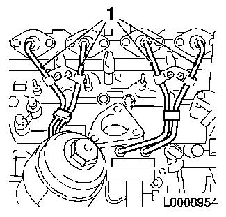
| 15. |
Remove high pressure lines (1), pressure chamber to
injectors
| • |
Unscrew 8x union nut with KM-812 or
KM-6098
|
| • |
Take out pressure lines
|
| • |
Seal 4x pressure chamber opening with protective cap
|
| • |
Seal 4x injector opening with protective cap
|
|
|
|
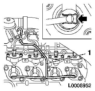
| 16. |
Detach fuel return line (1)
| • |
Detach 4x fuel return line from injector
| – |
Press 4x retaining clamps in direction of arrow
|
|
| • |
Detach fuel return line from pressure chamber
|
| • |
Unscrew 2x bolts
Note: Note different
bolt lengths
|
|
|
|
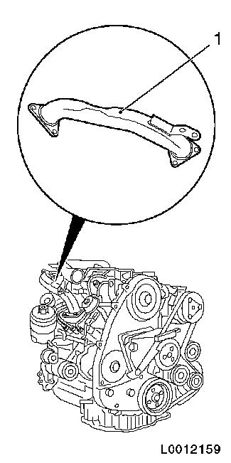
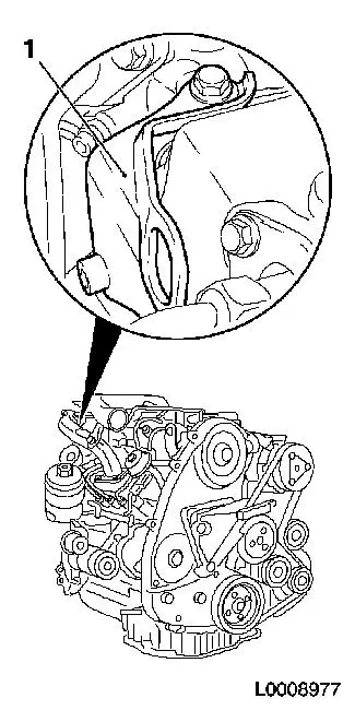
| 17. |
Remove rear right engine transport shackle (1)
|
|
|
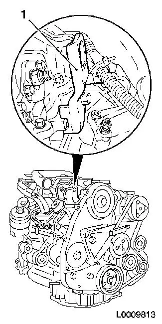
| 18. |
Remove rear left engine transport shackle (1)
|
|
|
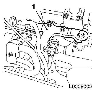
| 19. |
Remove bracket, oil dipstick guide tube (1)
| • |
Remove oil dipstick guide tube
|
| • |
Detach bracket, oil dipstick guide tube, from camshaft
housing
|
|
|
|
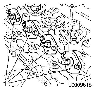
| 20. |
Remove 4x seals, connection for injectors (1)
|
|
|
| 21. |
Remove 4x seal, injectors (1)
|
|
|
| 22. |
Remove camshaft housing cover (1)
| • |
Unscrew 11x bolts
Note: Note different
bolt lengths
|
|
|
|
| 23. |
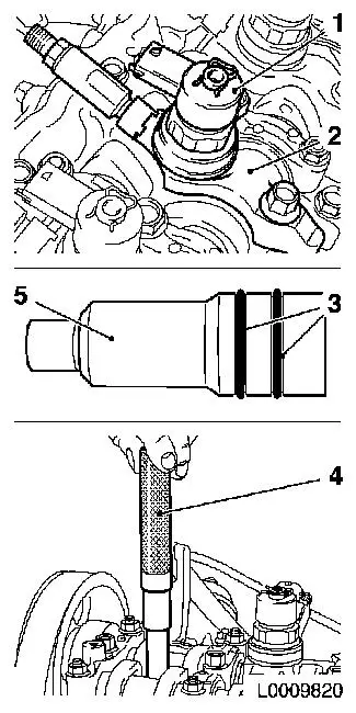
Remove injector (1)
Note: Mark
injectors
| • |
Remove injector bracket (2)
| – |
Unscrew bolt
Note: If a heat
protection sleeve (5) also has to be removed when removing an
injector, the gaskets (3) must be replaced and the heat protection
sleeve must be hammered into the cylinder head with KM-6357 (4)
|
|
|
|
|
 Install
| 24. |
Detach pressure chamber
| • |
Unscrew 2x bolts 1 - 1 1/2 turns
|
|
| 25. |
Replace injector gaskets
|
|
|
| 26. |
Install 4x injector
| • |
Install 4x brackets
| – |
Align injectors with EN-48560 (1)
|
|
|
|
|
| 27. |
Fasten 4x high pressure lines for pressure chamber to
injector
| • |
Fit 8x union nuts finger-tight
|
|
| 28. |
Fasten 4x injectors
| • |
Tighten 4x bolt in three stages
|
|
|
|
| 29. |
Fasten pressure chamber
|
| 30. |
Detach 4x high-pressure lines from pressure chamber to
injector
| • |
Seal off connections on pressure chamber with suitable sealing
plugs
|
| • |
Seal injector connections with protective caps
|
|
| 31. |
Clean sealing surfaces.
|
|
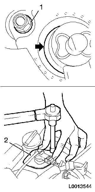
| 32. |
Apply sealing compound
Important: Oil return bore (2)
may not be covered with adhesive sealing compound
|
| • |
Apply adhesive sealing compound (white) to sealing surfaces (1)
and (3)
|
|
|
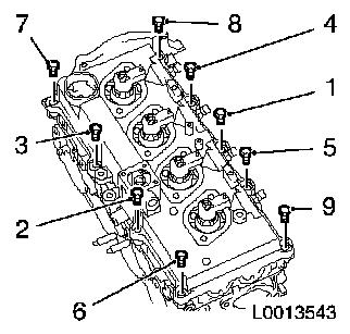
| 33. |
Install camshaft housing cover
| • |
Tighten 9x bolt in the stated order (1...9) 9.8 Nm
|
|
|
|
| 34. |
Install 4x new seal, injectors (2)
| • |
Align seal for injectors
Note: Sealing lip of
seal must be in full contact with the injector with no gaps
(arrow)
|
| • |
Coat 8x bolt head contact surface (1) with special grease
(white)
|
| • |
Tighten injector seal in 2 stages
Note: During the
tightening process, press injector seal against the camshaft
housing cover with your hand
| 1. |
Tighten 2x bolt 10
Nm |
| 2. |
Tighten 2x bolt 19
Nm |
|
|
|
|
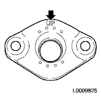
| 35. |
Install 4x new seal, connection for injectors
Note: Marking "UP" must
point upwards
|
|
|
| 36. |
Install bracket, oil dipstick guide tube
| • |
Attach bracket, oil dipstick guide tube, to camshaft
housing
|
| • |
Attach dipstick guide tube
|
|
| 37. |
Install rear left engine transport shackle
|
| 38. |
Install rear right engine transport shackle
|
| 39. |
Install fuel return line
Note: Note different
bolt lengths
| • |
Attach 4x fuel return line to injector
|
| • |
Attach fuel return line to accumulator
|
|
| 40. |
Install 4x high-pressure lines
Note: Attach first to
injector, then to pressure chamber
| • |
Detach 4x sealing caps from pressure chamber
|
| • |
Detach 4x protective caps from injector
|
| • |
Tighten 8x union nut with KM-812 or
KM-6098 25
Nm
|
|
| 41. |
Attach wiring harness for injectors
| • |
Connect 4x wiring harness plugs, glow plug
|
| • |
Connect 4x injector wiring harness plug
|
|
| 43. |
Install air intake pipe.
|
| 44. |
Install air cleaner housing with air intake hose
| • |
Attach water drain hose to air cleaner housing
|
| • |
Attach air intake hose to air intake pipe
|
| • |
Connect wiring harness plug to air mass flow meter
|
|
| 45. |
Install engine cover
| • |
Detach oil filler port closure cap
|
| • |
Attach oil filler port closure cap
|
|
| 46. |
Connect battery
| • |
Attach earth connection to earth terminal
|
|
| 47. |
Cooling System, Charge and Bleed
|
| 48. |
Program characteristic data of the new injector into the engine
control unit with TECH 2
|
Important: Wear protective
goggles
|
| 49. |
Carry out leak test on high pressure system
Note: Engine must be at
operating temperature
| • |
Carry out actuator test (fuel leak)
|
| • |
Visual inspection of high pressure system for fuel leak
|
|
| 50. |
Program volatile memories
|
1 ) Protective caps are available from the Opel
parts catalogue under catalogue number 45 06 154 / part number:
9201697
|
