|
Dismantle and assemble main shaft (F13/F13
MTA)
Note: Transmission
remains installed.
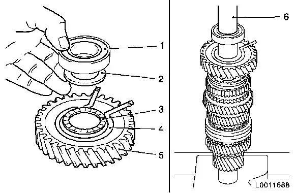
Overview of Drive Shaft
 Remove Remove
|
| 1. |
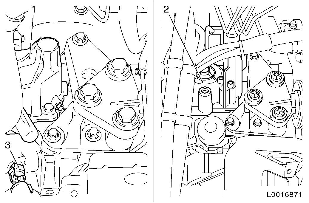
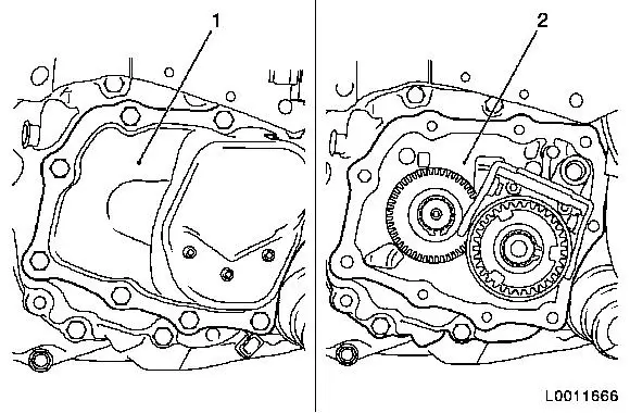
Remove gearbox cover (1)
Note: For F13
transmission.
Remove gearshift module (2)
Note: For F13 MTA
transmission.
|
| 2. |
Remove reversing lamps switch (3).
| • |
Disconnect wiring harness plug, reversing lamp switch
|
| • |
Unscrew reversing lamp switch
|
|
|
|
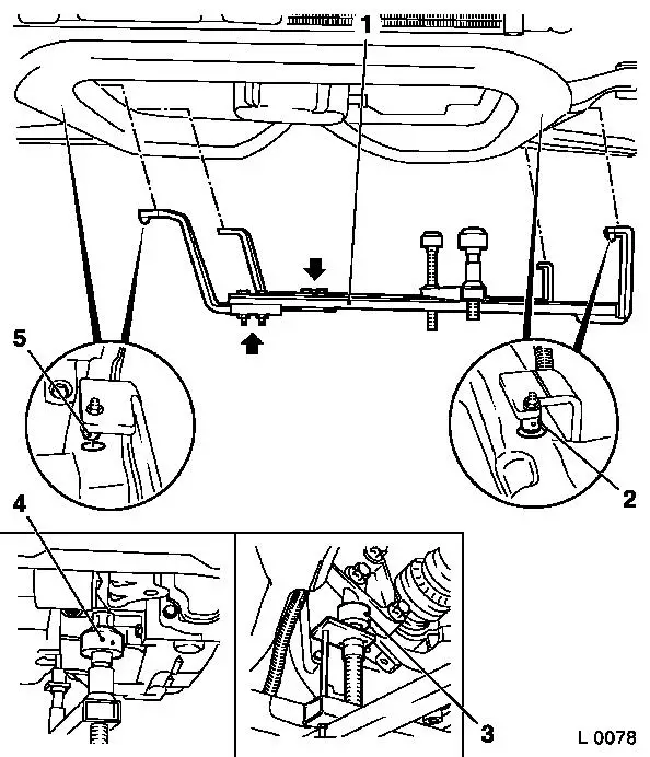
| 3. |
Attach KM-6001-B to front axle
body
Note: The guide pins
must sit in the support bearing with no play.
| • |
Release 2x bolt (arrows) for adjustment rails on KM-6001-B (1)
|
| • |
Insert KM-6001-B as shown
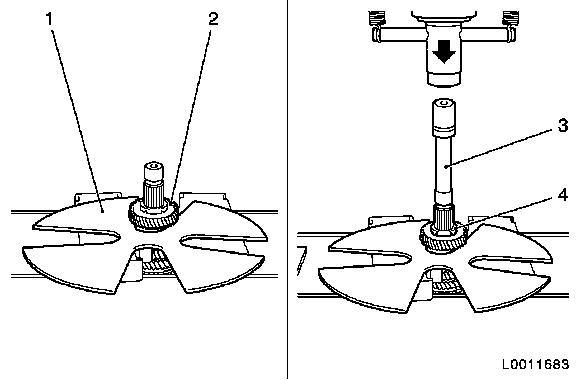
Note: 2x journals (2)
and (5) must sit flush in the guide holes of the front axle
body.
|
| • |
Tighten 2x bolt for adjustment rails
|
| • |
Twist up front support bearing (4)
| – |
until the guide pin is in contact with the front of the engine
damping block
|
|
| • |
Twist up rear support bearing (3)
| – |
until the guide pin is in contact with the rear of the engine
damping block
|
|
|
|
| 4. |
Remove front axle body
|
Important: Do not damage wiring
harnesses and attaching parts
|
| 5. |
Lower engine and transmission on the left hand side
|
|
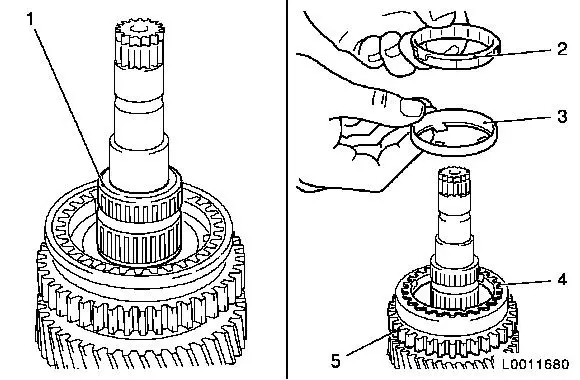
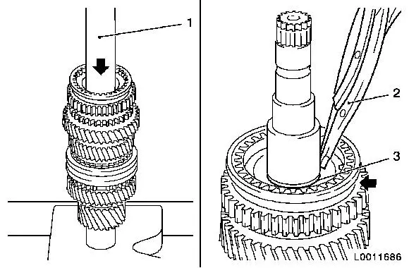
| 6. |
Remove end shield (1) cover 
|
|
| 8. |
Remove main shaft
Note: If the gear
wheels are damaged, the entire gear cluster must be replaced.
|
|
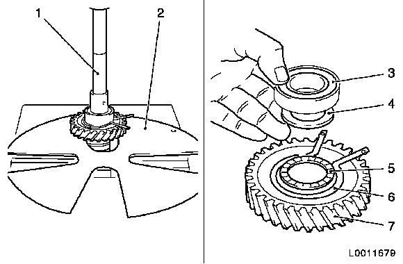
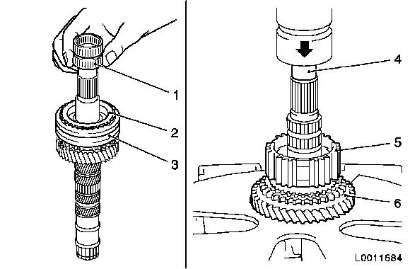
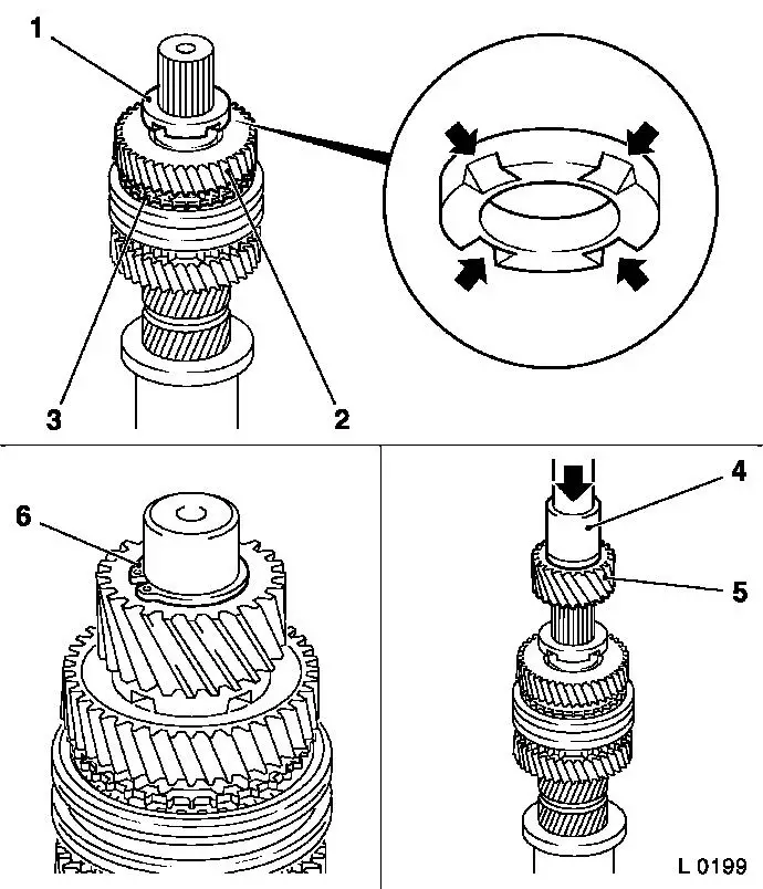
| 9. |
Detach gear wheel, 1st gear (7).
| • |
Press 1st gear off main shaft with KM-307-B (2) and KM-736
(1).
|
| • |
Remove ball bearing (3), and thrust washer (4)
|
| • |
Remove axial needle bearing (5) and retaining ring (6)
|
|
|
|
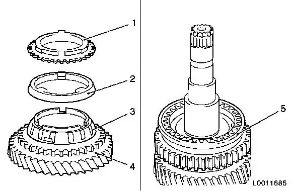
| 10. |
Detach 3x synchroniser ring, gear wheel, 1st gear
| • |
Remove needle bearing (1), inner synchroniser ring (2),
intermediate ring (3) and outer synchroniser ring (4)
|
|
|
|
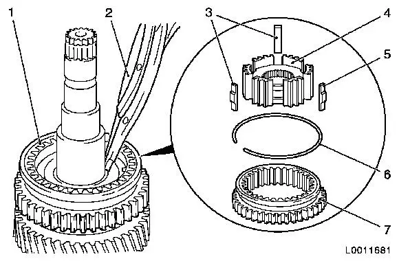
| 11. |
Detach synchro body (4)
| • |
Detach retaining ring (1) for synchro body 1st/2nd gear
assembly with KM-396 (2)
|
| • |
Detach shift sleeve (7)
|
| • |
Detach synchroniser spring (6)
|
| • |
Detach sliding blocks (3) and (5)
|
|
|
|
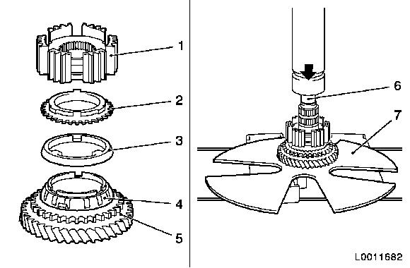
| 12. |
Detach 2nd gear (5).
| • |
Press gear wheel, 2nd gear, off main shaft with appropriate
drift punch (6) and KM-307-B (7)
|
| • |
Remove synchro body (1), inner synchroniser ring (2),
intermediate ring (3) and outer synchroniser ring (4)
|
|
|
|
Important: Always replace drive
wheels (driving and driven) in pairs.
|
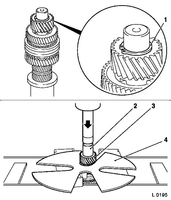
| 13. |
Detach drive wheel (driving) (3)
| • |
Press drive wheel off main shaft with appropriate drift punch
(2) and KM-307-B (4)
|
|
|
|
| 14. |
Detach 4th gear
| • |
Place KM-307-B (1) in groove with
gear wheel, 4th gear
|
| • |
Press gear wheel, 4th gear, and spacer washer (4) off main
shaft with appropriate drift punch (3) and KM-307-B
|
|
|
|
| 15. |
Detach needle bearing (1) from main shaft
|
| 16. |
Detach synchroniser ring, gear wheel, 4th gear (2)
|
| 17. |
Detach shift sleeve (3) from main shaft
| • |
Remove synchroniser spring and sliding blocks
|
|
| 18. |
Detach gear wheel, 3rd gear (6).
| • |
Press synchro body 3rd/4th gear (5), synchroniser ring and gear
wheel, 3rd gear, off main shaft with appropriate drift punch (4)
and KM-307-B
|
|
|
| 20. |
Check all parts for damage
Note: Replace damaged
components.
|
 Install
| 21. |
Immerse all parts in transmission fluid before
installation.
|
| 22. |
Lubricate all bearing bore holes and seating surfaces with
transmission fluid before installation.
|
|
| 23. |
Assemble synchro body 1st/2nd gear and 3rd/4th gear
Note: Synchro body
assembly 1st/2nd gear and 3rd/4th gear can only be pressed onto
main shaft in an assembled state
Overview of Synchronisation .
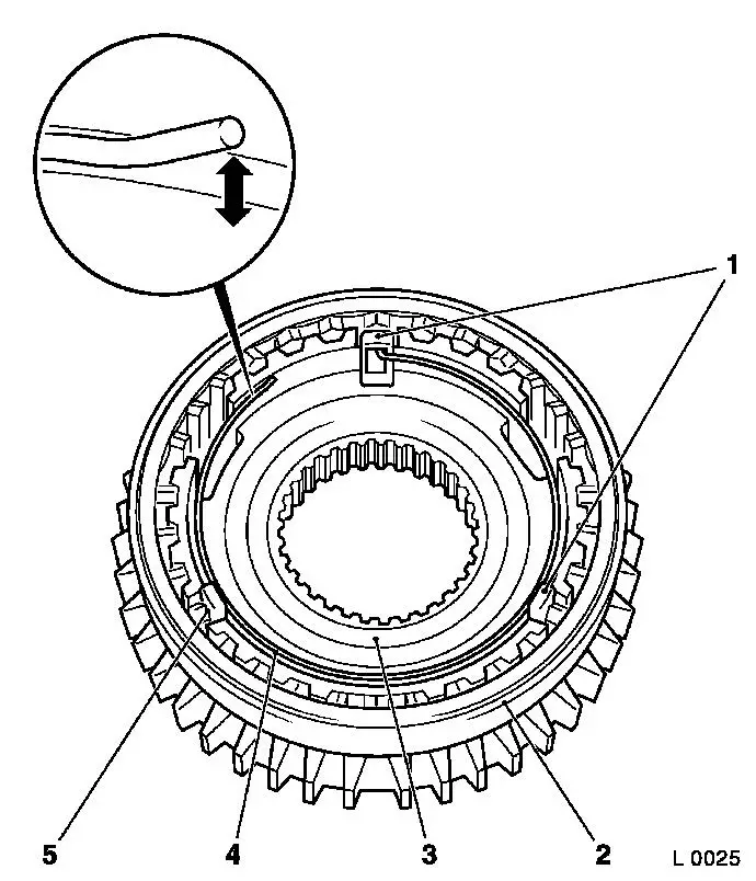
| • |
Insert synchro body (3) into shifter collar (2).
|
| • |
Insert 3x sliding block (1) and (5)
Note: Insert with the
open side facing the synchro body
|
| • |
Insert synchroniser spring (4)
Note: Ensure that when
installed in the correct position, the free end lifts off the
synchro body (arrow).
If this is not the case, turn synchroniser spring 180° and
reinstall.
Offset end of synchroniser engages in a slide block.
|
|
|
|
| 24. |
Attach gear wheel, 3rd gear (3), to main shaft
| • |
Attach needle bearing (2) for gear wheel, 3rd gear, to main
shaft (1)
|
| • |
Push gear wheel, 3rd gear, on to the main shaft from the drive
wheel side
Note: Cone (arrow)
points in the direction of the drive wheel
|
|
| 25. |
Press synchro body assembly for 3rd/4th gear (6) with KM-277 (5) onto main shaft.
| • |
Place synchroniser ring (4) onto 3rd gear cone.
|
|
|
|
| 26. |
Attach gear wheel, 4th gear (2), to main shaft
Note: Always replace
drive gears in pairs.
| • |
Attach needle bearing, gear wheel, 4th gear to main shaft
|
| • |
Attach synchroniser ring (3) to main shaft
|
| • |
Attach spacer washer (1) to main shaft
Note: 4x groove
(arrows) points to the gear wheel, 4th gear.
|
|
| 27. |
Attach drive wheel (5) to main shaft
Note: Collar points
towards the spacer washer.
| • |
Press drive wheel on to main shaft with KM-311-2 (4)
|
| • |
Attach retaining ring (6)
Note: Use new retaining
ring.
|
|
|
|
| 28. |
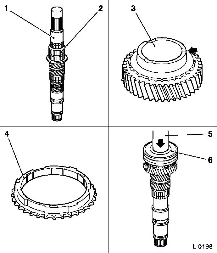
Attach gear wheel, 2nd gear (4), to main shaft
| • |
Attach inner synchroniser ring (3)
Note: Lugs must sit in
grooves of gear wheel.
|
| • |
Attach intermediate ring (2)
|
| • |
Attach outer synchroniser ring (1)
Note: Grooves must sit
on the lugs of the inner synchroniser ring.
|
|
| 29. |
Attach synchro body assembly (5) to main shaft
|
|
|
| 30. |
Press synchro body assembly on to main shaft with KM-277 (1)
Note: Lugs in outer
synchroniser ring must align with grooves in synchro body.
Shift fork groove (arrow) points towards the ball bearing seat
|
| 31. |
Attach retaining ring (3) with retaining ring pliers (2)
Note: Use new retaining
ring.
|
|
|
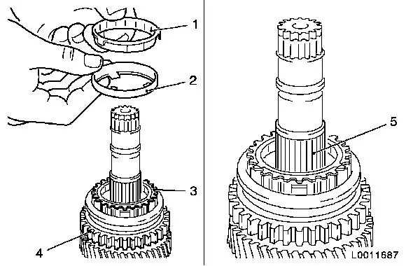
| 32. |
Attach outer synchroniser ring (3)
Note: Lugs must sit in
the grooves of the synchro body (4).
|
| 33. |
Attach intermediate ring (2)
|
| 34. |
Attach inner synchroniser ring (1)
Note: Lugs must sit in
the grooves of the outer synchroniser ring.
|
| 35. |
Attach needle bearing, 1st gear, (5) to main shaft
|
|
|
| 36. |
Attach 1st gear (5)
Note: Grooves must sit
on the lugs of the intermediate ring.
| • |
Attach axial needle bearing (3)
|
| • |
Attach spacer washer (2)
|
| • |
Fit new retaining ring (4)
|
|
| 37. |
Press ball bearing (1) on to main shaft with KM-334 (6)
|
|
|
| 38. |
Install end shield (2)
|
| 39. |
Attach end shield cover (1)
|
|
Important: Do not damage wiring
harnesses and attaching parts
|
| 40. |
Raise engine and transmission on the left hand side
|
| 41. |
Install front axle body
|
| 42. |
Detach KM-6001-B from front axle
body
|
|
| 43. |
Install gearbox cover (1)
Note: For F13
transmission.
Install gearshift module (2)
Note: For F13 MTA
transmission.
|
| 44. |
Fit reversing lamp switch (3)
| • |
Tighten reversing lamp switch
|
| • |
Connect wiring harness plug for reversing lamp switch
|
|
|
| 45. |
Correct transmission fluid level
|
|
